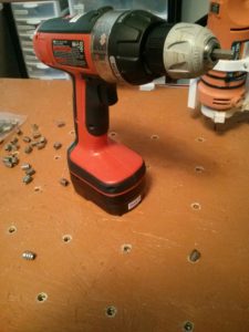
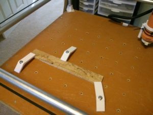
To easily hold stuff in place on the MPCNC, I used OpenSCAD to script it to drill a grid of 9mm holes in the bed, then I installed 1/4-20 threaded inserts into them. This lets me tighten down simple 3d-printed hold downs with normal 2″ bolts.
Category Archives: Random crap
MPCNC: new pen holder and trochoidal milling
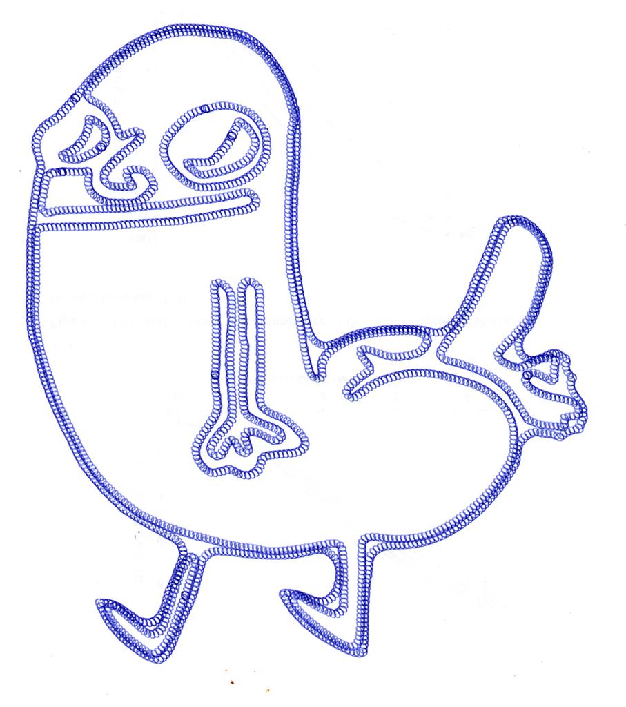
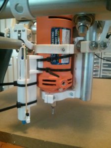 I improved the Z coupling, made a much better pen holder, and discovered trochoidal milling, which, in addition to making actual milling easier, draws cool pictures if used with a pen.
The pen holder was actually somewhat complex. The pen I wanted to use was a Bic 4-color, and its barrel has a very slight taper to it, so I had to model it fairly precisely and it took two prints to get the dimensions right. Now that it’s done, though, I can get really nice, repeatable drawings. I’m thinking of developing an algorithm to convert images into combinations of the pen’s four colors and emit gcode to approximate color printing. It will be ugly due to color theory (there’s a reason printers use cyan/magenta/yellow/black), but it might look neat.
Video/pic:
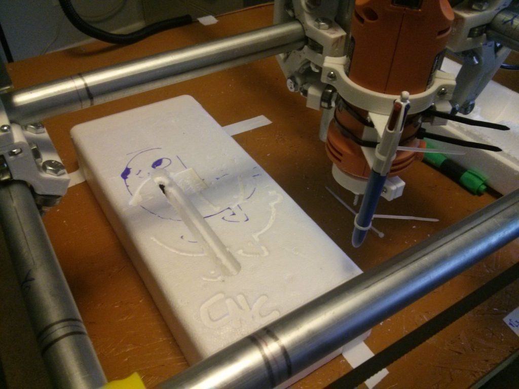
MPCNC: it drew this
The MPCNC with my rudimentary pen holder was able to draw this. I need to add some kind of spring downforce on the pen to deal with small differences in depth (which is why the lower left is faded). That should also help with pen accuracy, because on the high parts it’s grinding the pen too hard against the page and its getting stuck. I also need to turn up my overlap to get it to solid fill better.
MPCNC: Custom mods and part of a dickbutt
I’ve posted two custom parts for the MPCNC: a wire harness and a customizable end-stop holder.
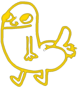
I tried a test run of the Optimal Fabrication Test Model (it’s dickbutt…we talked about this).
Results were…mixed. It started out strong by making key outline portions, so I left the room. I came back when I heard the spindle inexplicably struggling from downstairs. I come back to find the spindle has sunk all the way into the foam, and the nut that mounts the endmill to the tool has itself ground a sizable trench through the foam. Bits of foam are everywhere.
It turns out two separate failures happened. First, the Z coupler came loose…that’s my fault, as the plans called for nylon locknuts, but I couldn’t find any locally, so I used plain hex nuts, so the screws tightening it vibrated loose. Locknuts: ordered.
Second, there was a flaky connection on the X-axis, which is why it’s a vertical trench instead of a vaguely dickbutt-shaped trench. Apparently the wire I used doesn’t like to crimp well in Dupont connectors, so I crunched them all harder and added a bit of solder to be sure.
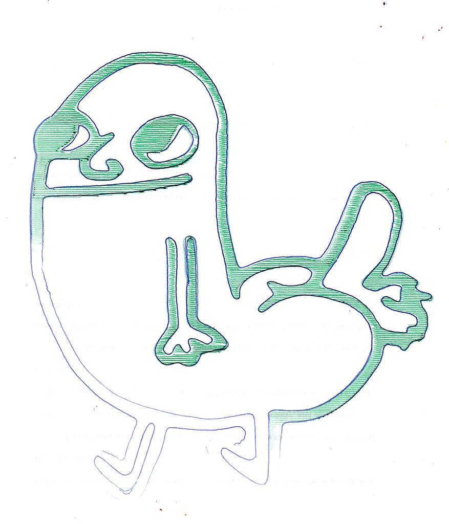
I 3D printed a pen holder to attach to the tool, so I can do ink-based tests while I work out the kinks. I did a dickbutt print on the same crappy foam, offsetting it a bit upward. The result is surprisingly good, given that the foam is nowhere near level, and I used the same program that assumes a 1/8″ endmill. Look at the solid ink on those eyes…nice!
Joining GT2 belt into closed loops
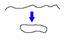
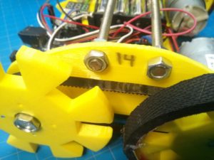
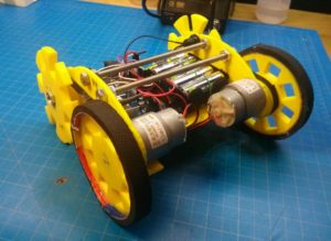
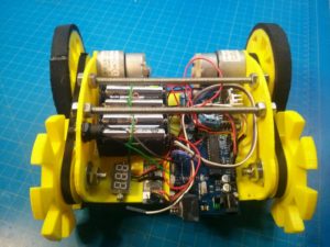
I was building a little robot, and I wanted belt-driven four-wheel drive using GT2 belt (an inexpensive timing belt common in 3D printers). The problem: I only had bulk GT2 belt, not closed loops (see extremely advanced diagram on right).
For my first attempt, I used end-slips to cut out the teeth from part of the belt, then super-glued it to the back of the other side. This works okay, but the joint was very inflexible owing to the near doubling of the thickness, and it eventually came apart after a few days use.
I’ve since found a better solution. What we need is a backing: a material I could adhere to the back of both sides of the belt, and which would be strong, flexible, and compatible with superglue.
I found such a substance in my trash can! When you buy 3D printing filament, it usually  comes vacuum-sealed in clear plastic to keep it dry. The parts of this plastic that have been heat-pressed together are strong and flexible without stretching — it’s the perfect belt backing!
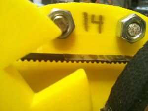
So I cut a narrow strip and super-glued it to the back of one end of the belt. Superglue dries hard, so I put down the glue in stripes so that the belt would still be flexible. After it dried a little, I glued the other end of the belt on, making sure to provide glue at the joint itself as well.
I let it dry under a weight for a few minutes, and the joint came out almost as flexible as the belt itself. The resulting bond has no give when stretched, goes over pulleys well, and survived the maximum tension I could put on the pulley by hand.
Pictures of belt on the end result (a little yellow robot):
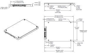
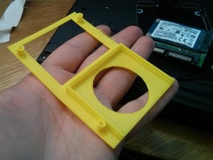
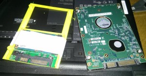
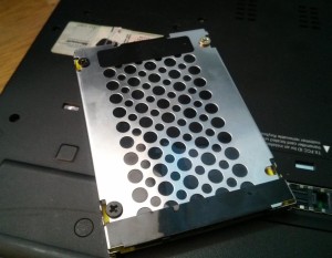
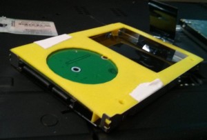
Adapting an mSATA card to a 2.5″ laptop bay
MC Escher “Concentric Rinds” in 3D
I recently saw the M.C. Escher exhibit at the NC Museum of Art, and one piece that stuck with me was Concentric Rinds:
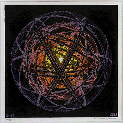
The geometry bugged me for a while until I finally figured it out and sketched it up in OpenSCAD:

Animated:
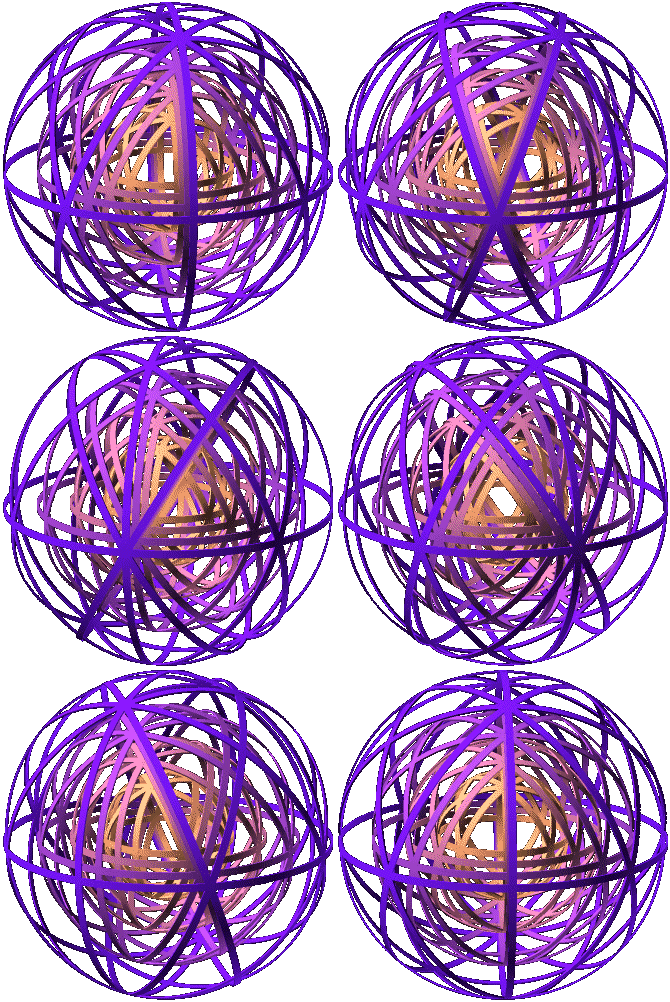
Here’s a cleaned up version of the OpenSCAD script to generate it – it’s surprisingly simple:
module torus_strip(r, width, thickness) {
    rotate_extrude(convexity = 10)
        translate([r, 0, 0])
        square([thickness,width], center=true);
}

module the_ring(r) {
    torus_strip(r, 2, 0.5);
}

$fn = 256;

rotate(180*$t)
for (r=[50,40,30,20]) color([1-r/50+0.5,1-r/50+0.1,r/50+0.1]) {

    rotate([ 0, 0, 0]) the_ring(r);
    rotate([90, 0, 0]) the_ring(r);
    rotate([ 0,90, 0]) the_ring(r);

    for (tt=[-60,-120]) rotate([0, tt, 0])
        for (t=[0:45:360-1]) rotate([ t, 0, 0])
            the_ring(r);

}
It took a while to figure out the geometry, but I finally got it when I saw there were three rings that were simply orthogonal, plus two arrays of 8 rings that intersected at the octagons. That’s how I modeled it above.
I also played with the animation stuff and got this:

Which I think is also neat.
That’s all.
3D crap
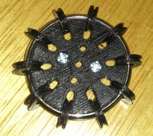 I got a 3D printer (a PrintrBot Simple Metal model 1403), and it’s been great. I don’t have time to write much, so I’ll share highlights:
- I’m on Thingiverse here. I’ve already put up a bunch of crap, including a customizable omni wheel design.
- I’ve been learning OpenSCAD, a free tool that lets you write code to generate 3D solids.
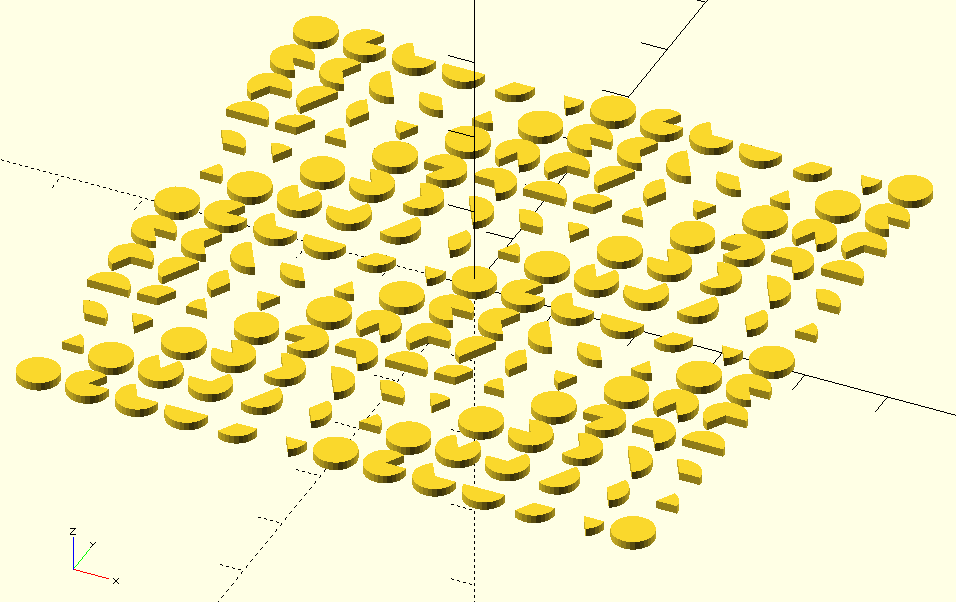
- There’s no arc function in OpenSCAD, and the solutions I found online were inefficient or only worked for certain inputs, so I wrote a new one. See below:
module arc(r,a1,a2,ir=0) {
    // normalize to 0..360 (even for negatives)
    a1n = (a1 % 360 + 360) % 360;
    a2n = (a2 % 360 + 360) % 360;
    difference() {
        circle(r);
        if (ir != 0) circle(ir); // if inner radius given, subtract it away

        // get the a1 to interpolate to, adding a revolution if going the long way
        a1next = a2n>a1n ? a1n + 360 : a1n;

        polygon([
            [0,0],
            [cos(1.00*a2n + 0.00*a1next)*2*r,sin(1.00*a2n + 0.00*a1next)*2*r],
            [cos(0.66*a2n + 0.33*a1next)*2*r,sin(0.66*a2n + 0.33*a1next)*2*r],
            [cos(0.33*a2n + 0.66*a1next)*2*r,sin(0.33*a2n + 0.66*a1next)*2*r],
            [cos(0.00*a2n + 1.00*a1next)*2*r,sin(0.00*a2n + 1.00*a1next)*2*r],
        ]);
    }
}

// test array
for (a = [-360:60:360], b = [-360:60:360]) {
    translate([a,b,0])  linear_extrude(height=10) arc(25,a,b);
}

