NOTE: Everything involved in this post is available for download here.
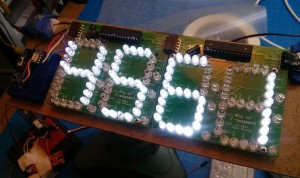 I while back, I made this PCB that acts as a big daisy-chainable two-digit 7-segment display using the WS2803D and discrete LEDs. The pic to the right is a shot of the first use of these PCBs: a big sign that says “4561”.
It works great, interfaces easily with AVR/Arduinos, and is cheap to build.
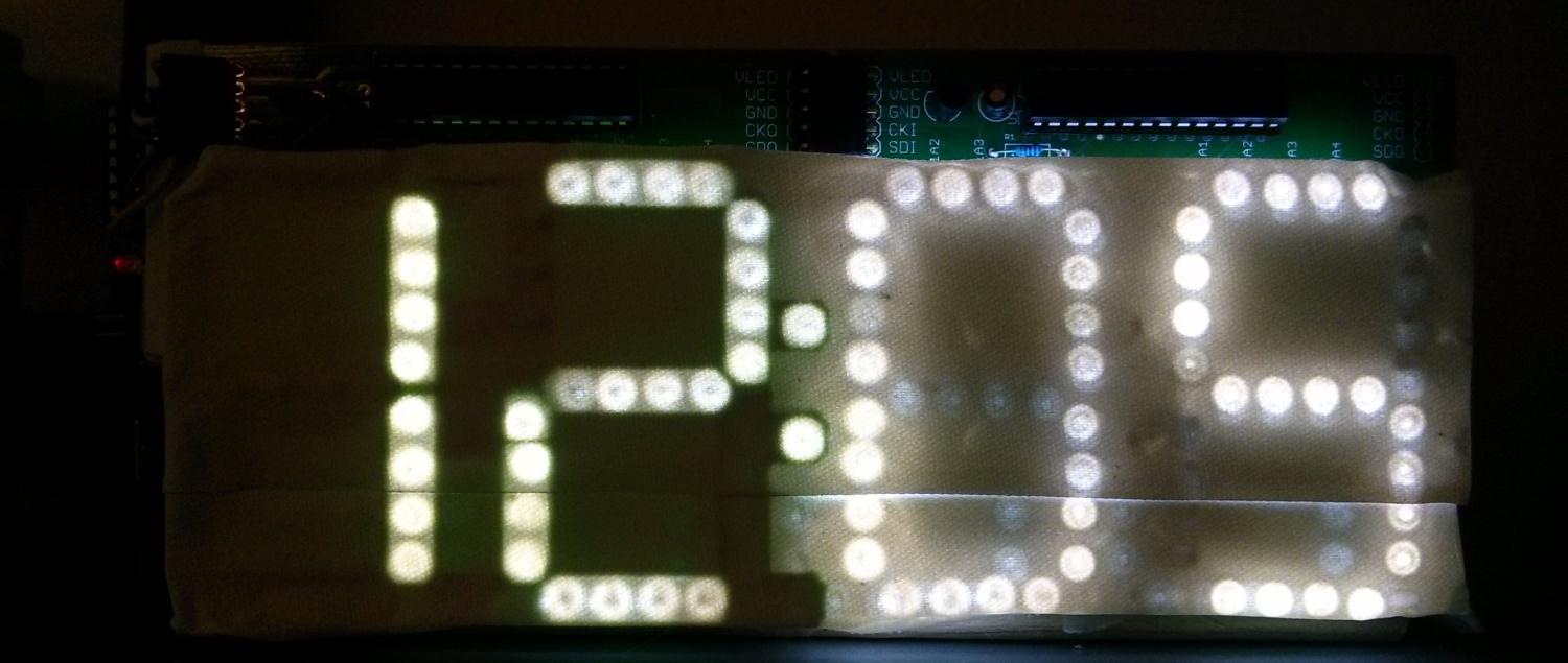
One thing that’s not great about it is the amount of light leakage from the LEDs — if you put some kind of light diffuser in front of it, you see all kinds of reflected and refracted bits of light. Here’s a shot of a clock I made out of these boards with white gaffer tape as a diffuser:
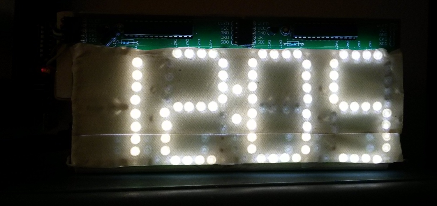
Look at all those random patterns of light…it’s shameful.
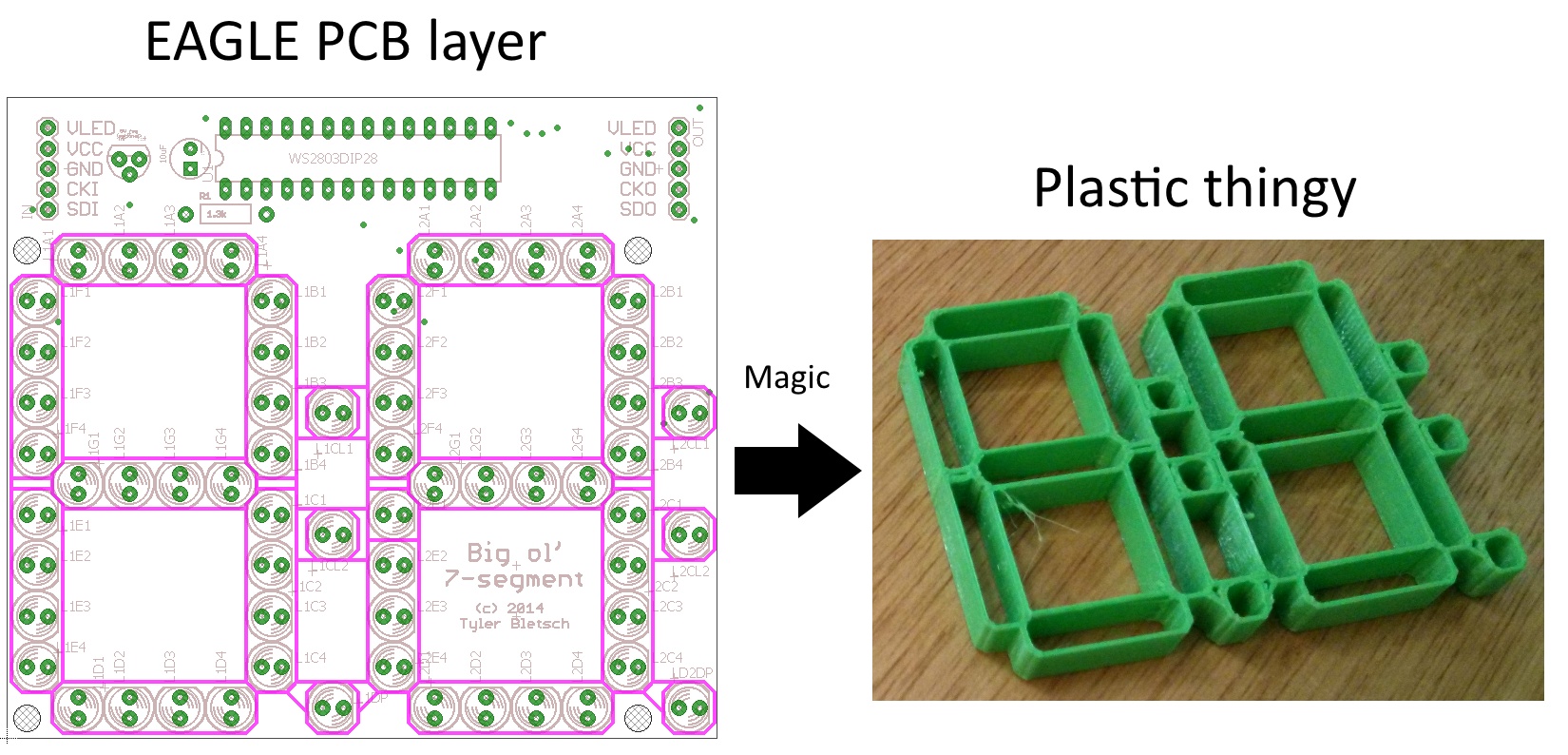
Today I figured out a simple way to 3D print a light mask for this board using design elements straight out of EAGLE! Here are the high-level steps:
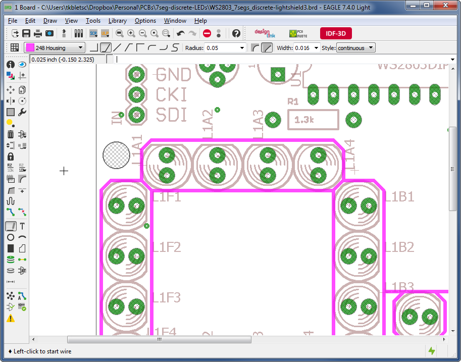
- In a new layer in your EAGLE board layout, draw the stuff you want to 3D print.
- Do a series of conversions to get that EAGLE layer turned into an OpenSCAD script and then a STL for printing.
- Print, jam on board, enjoy a better looking display.
Here’s a shot of the light mask applied to the left two digits of the clock:
Full directions after the break.
EAGLE is of course a 2D program, and we want to make a 3D thing. However, the thing in question is just a 2D form extruded into 3D, so we can actually draw the thing in EAGLE, then just say how tall it needs to be later. You’ll need three programs:
- EAGLE
- Inkscape
- OpenSCAD
 First, in Eagle:
- Draw whatever crap you want 3D printed on a separate EAGLE layer. I used the “Housing” layer (248).
- In the CAM processor:
- Select only the relevant layer
- Device = EPS
- Scale = 1
- File = “%N.eps” or whatever
- Click “Process Job”
This gives us an EPS file (a form of PostScript) with the 2D figure. Next, we use Inkscape to turn this into an OpenSCAD 3D design.
 Second, in Inkscape:
- Install paths2openscad. Download and extract to “%APPDATA%\inkscape\extensions” (Windows) or “~/.config/inkscape/extensions” (Linux/Mac).
- (Re)start Inkscape
- Drag the EPS file in, accept the default import settings
- Right click the thing and choose “enter group”
- Press Ctrl+A to select all pieces — they should all highlight separately.
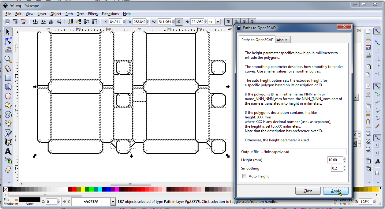
- From the Path menu, select Stroke to Path. It will think a bit to turn all those lines (which are 1D strokes with thickness) into paths (which are true 2D forms).
- From the Extensions menu, select “Generate from Path” > “Paths to OpenSCAD”. Accept the defaults, setting height as you see fit. Export the OpenSCAD file.
Now we have an OpenSCAD script.
 In OpenSCAD:
- Load the thing
- Render the thing
- Export as STL
Then just 3D print it up! For this particular thing, I set my line width in EAGLE to 0.016″ (~0.4mm), which is the size of my 3D printer’s nozzle. That meant that every line was a single pass of the printer.
What doesn’t work
I thought I’d vent for a bit on the many, many ways of doing this that did not work:
- EAGLE can export a DXF file, and OpenSCAD supports import of DXF, so you might think you can skip the whole Inkscape nonsense. Not so — EAGLE uses DXF commands that OpenSCAD doesn’t understand.
- Similarly, Inkscape’s DXF import also chokes on EAGLE DXF files.
- You might think you could somehow post-process the DXF into a more normal format and extrude it using another CAD package. This is probably possible somehow, but all the toolchains I tried failed at one point or another.
- Converting DXF using QCAD didn’t work, despite QCAD supporting like 20 flavors of DXF.
- Converting from DXF to SVG using QCAD worked, but then my “trial” of that feature expired, as if exporting to SVG is worth 33 freakin Euros.
- You can do QCAD DXF import -> QCAD PDF export -> Inkscape import, but it’s long and awkward, especially with QCAD’s weird handling of units.
- Many 3D CAD packages’ attempts to load the DXF would turn it into a pile of rods, ignoring the whole “lines that make up the shape” aspect. I’m looking at you, TinkerCAD.
- Online web-based format converters often butchered the form entirely.
- I tried to use Blender HAHAHAHAHAHA what a nightmare.
- FreeCAD is a literal warcrime.
Pingback: Fitting 3D Prints On Eagle Boards | Hackaday
Really nice work