Circuit boards, even small ones, look crazy complicated. But they really aren’t — they’re just efficiently packed. Most circuit boards have just two “layers” of copper traces running around: top and bottom. Something sophisticated like a computer motherboard can have more copper sandwiched in the middle, but most of the things a hobbyist would want to trace are just have a top and bottom.
What can make tracing complicated is that the two sides work together, with a single connection flipping between top and bottom multiple times. But we can use a camera and an image editor like Paint.NET, Photoshop (the CS2 version is free now), or GIMP to make it easy.
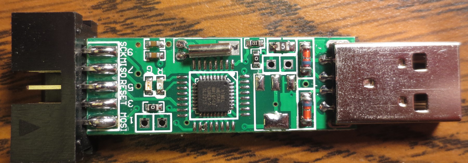
As an example, let’s trace this USB device. It’s an off-brand programmer for AVR chips that had no documentation and didn’t work in a standard way like similar products, so I had to figure to figure out how it was wired up.
I started by taking good, high-resolution pictures of each side, trying to keep the camera a fixed distance from the board on each side. Using a document scanner didn’t work for this, because the board didn’t lie flat on the glass…you might be able to use a scanner for a flatter circuit board.
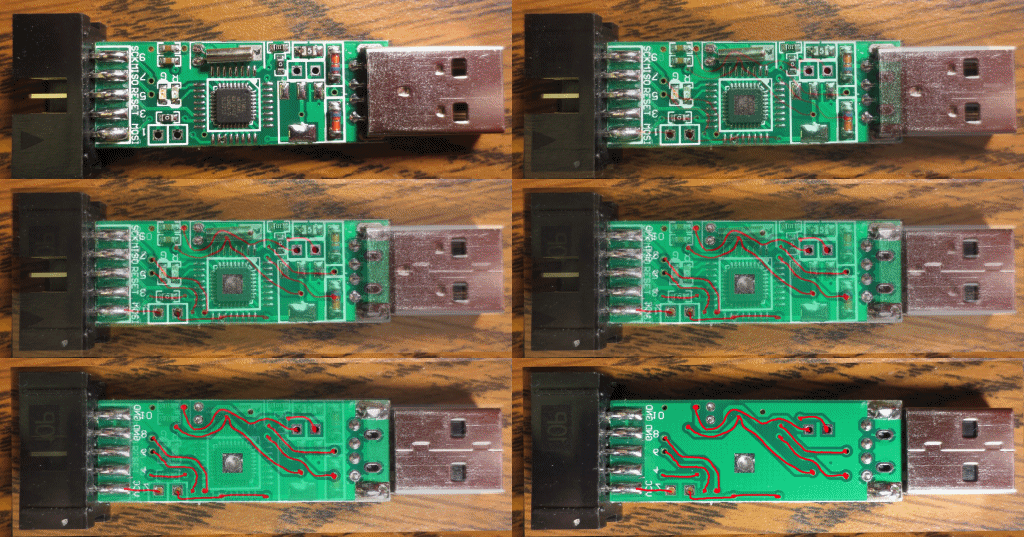
We’re going to superimpose the bottom (simple) side over the top (complex) side in the image editor. Take the picture of the simple side, copy it, and paste it as a new layer over the complex pic. Set it to semi-transparent, flip it vertically, then use the layer transform or move tool to get it to line up exactly over the top side of the board. Be sure to match up key landmarks, like vias (the little holes that connect top and bottom) and through-holes.
Once they match, turn the simple side opacity all the way back up, add a new empty layer, and paint all the traces you see in a high-contrast color (like red, for green boards). When you’re done, you should be able to slide the opacity of the simple & red layers up and down and have it look like this:
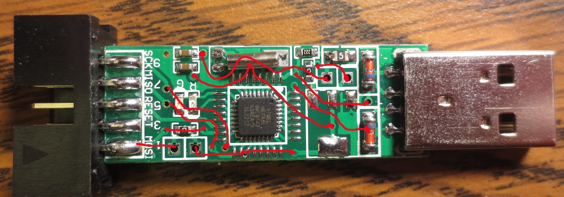
Now, turn off the simple layer, but keep the red trace layer. Now you have a picture of the top of the board with all the bottom-side traces super-imposed:
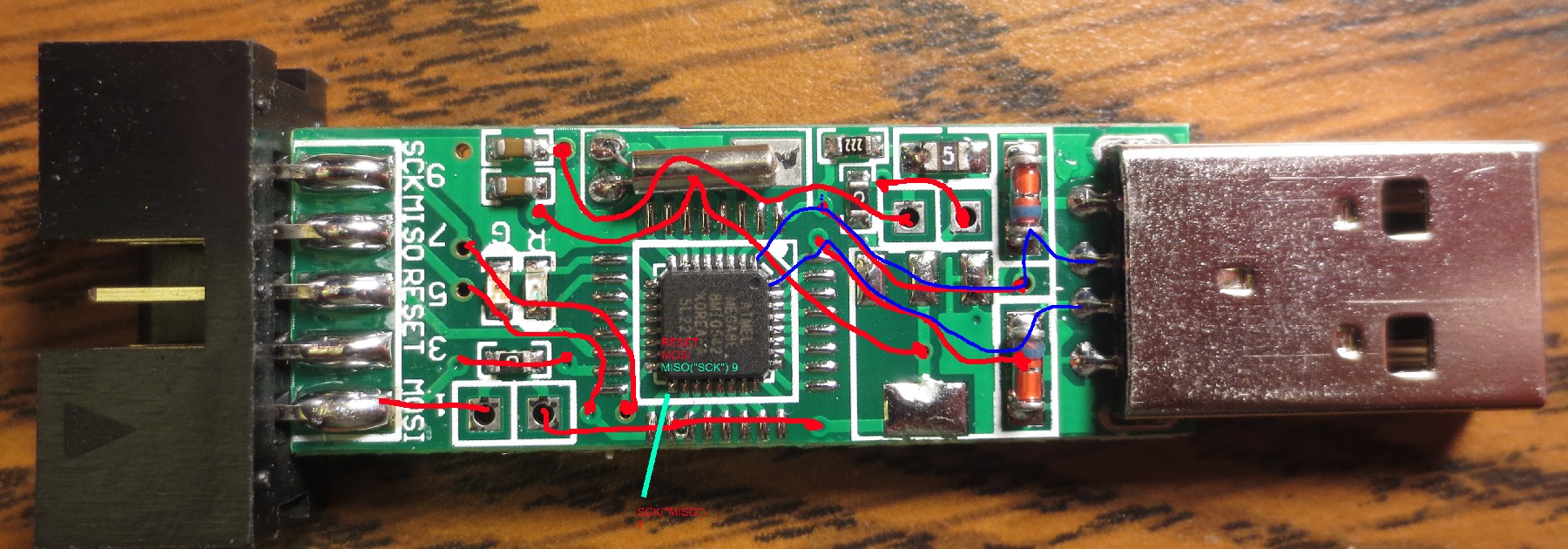
Now you can add another layer and draw additional annotations that you need until you’ve discovered everything you need to know.
What I needed to know for this board was this: I was dumb to buy this $4 programmer just because it had a fancy case when the well-known good model was nine cents cheaper. It’s a crappy nonstandard board nobody’s ever heard of, and though I could fix it by adapting custom firmware for it, I’m better off just throwing it in the bin and getting the good one (which I did).
But it was a good exercise in circuit tracing.


