(Wow, just found out that this made Hack A Day, cool!)
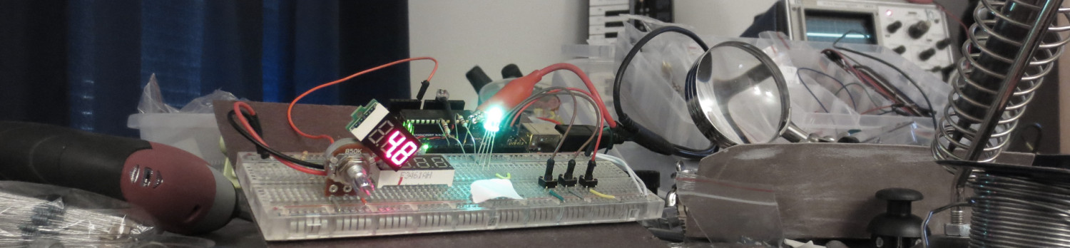
I just finished the Nickelphone! It’s a coin-based music keyboard. 15 nickels and 10 pennies act as touch sensors on a traditional 25-key piano-style layout. It can emit simple square wave tones through an onboard piezo buzzer, but its primary use is as a MIDI keyboard, so it can drive a full synthesizer (like FL Studio on PC). It’s based on an ATmega644 microcontroller, chosen because each key needs its own pin, and this chip has 32 data pins (8 of them analog inputs). (Also, it happens to be the chip I got for free in when I placed my Atmel free sample order.) It uses the “no extra parts” capacitive sensing method developed by Mario Becker and others. For the MIDI output, I used the “last darned MIDI interface I’ll ever build” by Stephen Hobley (just the output part, which just uses one resistor). The software is written in Arduino, with the “core” for the ATmega644 chip being adapted from the Sanguino project. The Nickelphone was inspired by Linus Åkesson’s Chipophone and its follow-on, the bitbuf, both of which are totally awesome.
Read on for details…
The final parts list ended up being:
- ATmega644 ($7.98 from Digikey or free from Atmel as a sample)
- About half a 25ft spool of 22AWG solid core hookup wire (~$5 for the spool) — plugs directly into the breadboard!
- A 400-point breadboard (about $2.50 on ebay)
- A mini 170-point breadboard (about $1 on ebay)
- A breadboard-able MIDI port ($2 on ebay)
- A tactile button for a reset button (optional)
- A toggle button to enable/disable the piezo
- A piezo buzzer
- Some LEDs
- Two few-hundred-ohm resistors for the LEDs (I think I used 220 and 470?)
- A 220 Ω resistor for the MIDI out
- A 10uF decoupling capacitor (works fine without it, but whatever)
- A 5V DC adapter “wall wart” (free if you keep old DC adapters (you do, right?))
- A piece of particle board left over from an old desk
- 15 nickels ($0.75)
- 10 pennies ($0.10)
So all told, it only cost me about $12 to build, probably about $25 if I didn’t have any parts at all to start with.
I’ll relate the build process and a few lessons learned along the way.
Build process
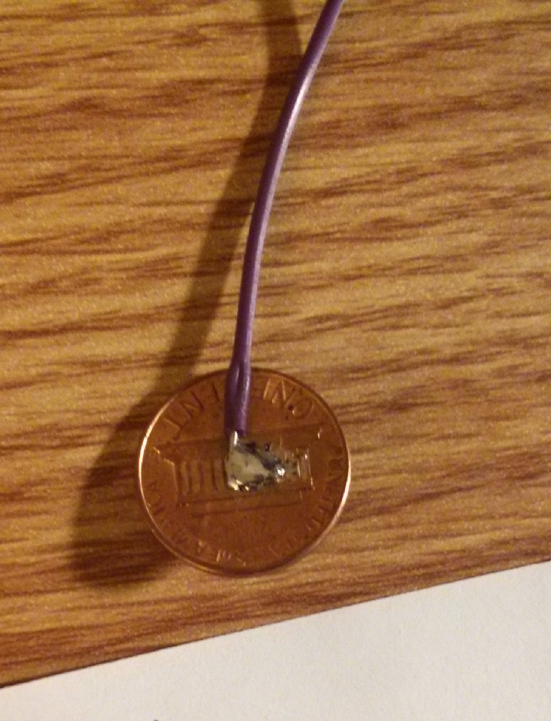
I started out by doing a proof of concept. I soldered a few nickels to the solid-core wire. The easiest way to do this is to “tin” the coin first, heating it up a bunch with the iron, melting some solder on top, and blobbing it around until it’s flat. Then I laid a hook of wire over it, melted it in, added a little solder on top, and that was it. Unlike wire solders, coins hold a bunch of heat, so cool them with a wet paper towel before handling! I somehow only burned myself once.

I started out using the Capacitive Sensing library for Arduino, which uses a a send pin and an array of receive pins; resistors are placed between the single send pin and each receive pin. This involved a lot of 1MΩ resistors, which sucked to pack in there. I wrote a little Arduino program to play a few square wave frequencies when these five nickels were pressed out the piezo buzzer. It worked!
Next, I found the dimensions of the coins and laid them out in Visio. I printed out the layout, cut it in the center of the coin outlines, and marked the edges of where the coins would sit on the wood.

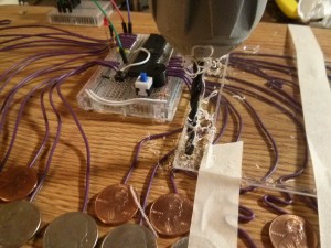
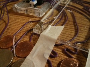
Then I soldered the rest of my coins. I roughly measured out a length of wire for each coin so it would reach the general area where the breadboard would be. I didn’t plan very precisely, but it turned out fine. I hot glued all my coins in place.

 Since I was relying on separate resistors for each pin, I could only hook up about five coins at this point. I needed to pack a ton of 1MΩ resistors on there! Luckily, I found out about resistor arrays, which are a bunch of resistors all hooked to a common pin in one compact package. I got a bunch of 9-pin (8 resistor) arrays for $6. (I’d later find a way to ditch external resistors altogether, but we’re not there yet.)
Once they arrived, I was able to get the rest of the coins hooked up. I needed to get creative to get all 25 wires to go through resistor arrays to a single sending pin. I used three of the corners of the chip — each of these corners had an array with the common pin jutting out. I snipped with the arrays with wire cutters to the correct number of resistors…I was surprised to find it actually worked!


This build is what played the demo in this work-in-progress video:
One problem I had was detecting multiple presses. I set my program to output the detected press levels of each coin and printed them via serial (through a TTL serial to USB adapter) to my terminal. I found that unpressed coins were around 2-10 while a single pressed one was around 600 — easy to detect. The issue was that (a) coins next to the pressed coin would sometimes jump to 30-50 and (b) the more coins you pressed, the lower the press value for each. That is, pressing two at once would give around 300, three would give around 200, etc. When you got to about 5 presses at once, it would be hard to distinguish pressed keys from unpressed ones.
I eventually figured out the problem. The human body has about 2 MΩ resistance between any two points (basically it’s 1 MΩ to get into the skin, near zero ohms inside our squishy bodies, them 1MΩ to get out somewhere else). Each pin is measured one at a time, but that doesn’t stop the other pins from being in the circuit when you’re touching more than one. See this excellent, high quality diagram:

In figure 1, we’re touching two nickels. Let’s assume we’re measuring receive pin 1. Because of the resistance of the hand, this is equivalent to the circuit in figure 2 — the 1 MΩ resistor we installed, plus 3 MΩ of the other nickel plus the hand. This, in turn, is equivalent to the circuit in figure 3. Our resistance between send and receive has been cut! Worse, the more pins you touch at the same time, the lower the resistance gets, and the numbers you see approach the “noise” in the rest of the circuit, meaning you can’t reliably detect 5 or more presses at a time. This is totally unacceptable for a musical instrument — music people press multiple keys all the time! (Not me, because I suck, but I mean real music people.)
So I needed a way to not share a common send pin, but if I had a send+recv pin for each coin, I’d need 50 inputs, which I did not have. That’s when I remembered a capacitance sensing hack I’d read about based on using the internal pullup resistor of the ATmega. Mario Becker and others developed an ingenious bit of code which turns the pin into an output, sets it low, then turns it into an input with a pullup resistor (as though you’re detecting a traditional button) and counts the clock cycles until it registers as high. The timing is close to the clock rate of the chip (8MHz for me), so they unroll the detection loop and address everything directly via the ATmega control registers. The upside is that it requires NO additional parts and has (internally) a separate “send” and “receive” pin (really the input and output functions of the chip itself). Their code:
uint8_t readCapacitivePin(int pinToMeasure) { // Variables used to translate from Arduino to AVR pin naming volatile uint8_t* port; volatile uint8_t* ddr; volatile uint8_t* pin; // Here we translate the input pin number from // Arduino pin number to the AVR PORT, PIN, DDR, // and which bit of those registers we care about. byte bitmask; port = portOutputRegister(digitalPinToPort(pinToMeasure)); ddr = portModeRegister(digitalPinToPort(pinToMeasure)); bitmask = digitalPinToBitMask(pinToMeasure); pin = portInputRegister(digitalPinToPort(pinToMeasure)); // Discharge the pin first by setting it low and output *port &= ~(bitmask); *ddr |= bitmask; delay(1); // Prevent the timer IRQ from disturbing our measurement noInterrupts(); // Make the pin an input with the internal pull-up on *ddr &= ~(bitmask); *port |= bitmask; // Now see how long the pin to get pulled up. This manual unrolling of the loop // decreases the number of hardware cycles between each read of the pin, // thus increasing sensitivity. uint8_t cycles = 17; if (*pin & bitmask) { cycles = 0;} else if (*pin & bitmask) { cycles = 1;} else if (*pin & bitmask) { cycles = 2;} else if (*pin & bitmask) { cycles = 3;} else if (*pin & bitmask) { cycles = 4;} else if (*pin & bitmask) { cycles = 5;} else if (*pin & bitmask) { cycles = 6;} else if (*pin & bitmask) { cycles = 7;} else if (*pin & bitmask) { cycles = 8;} else if (*pin & bitmask) { cycles = 9;} else if (*pin & bitmask) { cycles = 10;} else if (*pin & bitmask) { cycles = 11;} else if (*pin & bitmask) { cycles = 12;} else if (*pin & bitmask) { cycles = 13;} else if (*pin & bitmask) { cycles = 14;} else if (*pin & bitmask) { cycles = 15;} else if (*pin & bitmask) { cycles = 16;} // End of timing-critical section interrupts(); // Discharge the pin again by setting it low and output // It's important to leave the pins low if you want to // be able to touch more than 1 sensor at a time - if // the sensor is left pulled high, when you touch // two sensors, your body will transfer the charge between // sensors. *port &= ~(bitmask); *ddr |= bitmask; return cycles; }When it comes to multi-press detection, things actually get better the more keys you press. When unpressed, a coin returns 1, when a single coin is pressed, it returns around 3-4. However, when multiple coins are pressed, each returns 17 (the maximum output of the function)! I believe this is because the pins not being measured are being held low, so the body is actually holding the pin being measured to ground through its 2 MΩ resistance, greatly slowing how long it takes to charge. (If allowed more time to charge, I suspect the pin would eventually make it to 5V, since the internal pullups are around 20 kΩ to 5V and the body is 2 MΩ to ground.) This led to absolutely fantastic reliability.
With this, all that was left was to add MIDI output and some polish. I used a separate mini breadboard with a breadboard-able MIDI port, since the coin wires forced the main breadboard to be oriented vertically, and I wanted the MIDI port to be facing back. (Also mini breadboards are dirt cheap, so whatever). I followed Stephen Hobley’s MIDI circuit (the output part only).
Dumb side note: I didn’t look closely at Stephen’s design, and assumed I’d need the opto-isolator he used. Turns out you only need it for input, so now I have a bunch of those sitting around. Whatever.
All that was left was to set the serial port to MIDI speed (31250 bps) and output the correct control codes when keys were pressed and unpressed. I didn’t bother with a MIDI library, since I just needed note on and off — I just sent the bytes directly based on “David’s MIDI spec”, a very useful reference.
I had to do a bit of logic to turn the capacitance sensing values into key-down/key-up messages. This was as simple as storing the previous key state in each and comparing it to the current state each trip through the loop:
for (int i=0; i<cs_count; i++) { total[i] = cap_sense(i); } for (i=0; i<cs_count; i++) { boolean bstate = total[i]>=threshold; if ( bstate && !button_state[i]) key_down(i); if (!bstate && button_state[i]) key_up(i); button_state[i] = bstate; }With this, I was able to play anything I wanted and have it rendered in beautiful fancy-pants sound in FL Studio:
All that was left was to pretty it up. I added an onboard speaker toggle button and reset button (since it calibrates on reset) and trimmed the leads on the components.
I had previously been powering it via the USBasp programmer that I used to flash the chip — that had to go. I wanted to put on some kind of nice DC barrel connector or USB connector, but I couldn’t find anything breadboard-able and I didn’t want to solder any protoboards, so I stuck a 5V DC adapter right on it. Just cut off the end, soldered the two wires to some 0.1″ pins, and finished it with headshrink tube and hot glue. Then I secured it in place mechanically by tying a knot, and zip-tying the cable to the board.
To keep the coin wires tacked down, I was going to do something fancy with polycarbonate, but I suck at actually fabricating stuff, so I ended up screwing two CD jewel case tops into it with PC fan screws. I took the wires and bent them to they all had a flat path to the breadboard. Then I taped the jewel cases in place and drilled four holes in each where I thought made sense. I used a 11/64″ drill bit for the fan screws (determined experimentally in a piece of scrap board). You have to drill the jewel cases slowly and lightly, since they’re brittle, then go crazy when you get to the wood. I then took them off, blew the whole thing out with compressed air, and screwed them back down. They got a few cracks, so we’ll see if they hold up.
Lastly, I soldered some wire to 0.1″ pins to form the connection between the MIDI out board and the main board, then stuck some labels on it, which gives us the finished product:
Chip config
So I built this out of an ATmega644 chip, but I wanted to program in Arduino rather than plain C. This requires the use of a “core” — a collection of files that describe the hardware in Arduino terms. Luckily, the Sanguino project uses a nearly-identical same chip, but I had to modify their core because my use of the chip was a bit different:


- I wasn’t using an external crystal oscillator, so the hardware description had to change (boards.txt).
- I wasn’t using the Arduino boot loader or firmware, since I’m programming it natively with a USBasp.
- I didn’t need any of the stuff in “cores” (I guess…it seemed redundant so I stripped it out and it worked).
- I’m using an ATmega644 rather than the Sanguino’s ATmega644P, the latter apparently adding a few minor features and needing less power.
So I took the Sanguino core, renamed it “atmega644_naked”, and stripped it to just two files: “boards.txt” and “variants/atmega644/pins_arduino.h”.
The pins file was unmodified. For the boards file, I started with the naked ATtiny85 file from here and tweaked it, since the Sanguino one was very complex (likely because the Sanguino integrates its own programming hardware). My boards file:
atmega644_1.name=ATmega644 naked (int 1 MHz) atmega644_1.bootloader.low_fuses=0x62 atmega644_1.bootloader.high_fuses=0xd9 atmega644_1.bootloader.extended_fuses=0xff atmega644_1.upload.maximum_size=65536 atmega644_1.build.mcu=atmega644 atmega644_1.build.f_cpu=1000000L atmega644_1.build.core=arduino:arduino atmega644_1.build.variant=atmega644 atmega644_8.name=ATmega644 naked (int 8 MHz) atmega644_8.bootloader.low_fuses=0xe2 atmega644_8.bootloader.high_fuses=0xd9 atmega644_8.bootloader.extended_fuses=0xff atmega644_8.upload.maximum_size=65536 atmega644_8.build.mcu=atmega644 atmega644_8.build.f_cpu=8000000L atmega644_8.build.core=arduino:arduino atmega644_8.build.variant=atmega644The fuse values listed select chip options such as clock rate and debug features. I used the Engbedded AVR Fuse Calculator to figure these out. One tricky part was that I noticed four of my data pins weren’t working. I eventually figured out from the datasheet (page 78) that this was because those pins were for JTAG debugging support. To get those pins back, I just needed to change the fuse values using the fuse calculator. To actually set the fuses, you can use avrdude directly (included with the Arduino distribution) or put the desired values into the boards file above then choose “burn bootloader” (which, since we have no bootloader, just sets the fuses).
Once this was done, the chip was ready to use with Arduino.
Software
Once I worked out the capacitance sensing kinks, the code was fairly straightforward. I used a few preprocessor macros to toggle debug mode on/off (off means it emits MIDI at 31250 bps, on means it emits text at 57600 bps). The rest of the code is fairly straightforward — feel free to email me if you have any questions. Here’s the whole thing:
#include <stdint.h> #define SERIAL_DEBUG 0 #define DEBUG_VERBOSE 1 #define DEBUG_COLOR 1 // 0 = oscillate with sense cycle // 1 = on if any key is down #define LED_MODE 1 #if SERIAL_DEBUG #define debug_print(v) { Serial.print(v); } #define debug_println(v) { Serial.println(v); } #else #define debug_print(v) { } #define debug_println(v) { } #endif int base_c_note = 48; // the MIDI note code for the bottom C of the instrument, 60=middle C // ATMEL ATMEGA644P / SANGUINO // // +---\/---+ // INT0 (D 0) PB0 1| |40 PA0 (AI 0 / D31) // INT1 (D 1) PB1 2| |39 PA1 (AI 1 / D30) // INT2 (D 2) PB2 3| |38 PA2 (AI 2 / D29) // PWM (D 3) PB3 4| |37 PA3 (AI 3 / D28) // PWM (D 4) PB4 5| |36 PA4 (AI 4 / D27) // MOSI (D 5) PB5 6| |35 PA5 (AI 5 / D26) // MISO (D 6) PB6 7| |34 PA6 (AI 6 / D25) // SCK (D 7) PB7 8| |33 PA7 (AI 7 / D24) // RST 9| |32 AREF // VCC 10| |31 GND // GND 11| |30 AVCC // XTAL2 12| |29 PC7 (D 23) // XTAL1 13| |28 PC6 (D 22) // RX0 (D 8) PD0 14| |27 PC5 (D 21) TDI // TX0 (D 9) PD1 15| |26 PC4 (D 20) TDO // RX1 (D 10) PD2 16| |25 PC3 (D 19) TMS // TX1 (D 11) PD3 17| |24 PC2 (D 18) TCK // PWM (D 12) PD4 18| |23 PC1 (D 17) SDA // PWM (D 13) PD5 19| |22 PC0 (D 16) SCL // PWM (D 14) PD6 20| |21 PD7 (D 15) PWM // +--------+ // byte pin_cs[] = {0,1,2,3,4,5,6,7,10,11,12,13,14,16,17,18,19,20,21,22,27,28,29,30,31}; // pins used for the coins byte pin_speaker = 15; // speaker pin, must be PWM-capable byte pin_led = 23; // LED pin, used as an indicator const int cs_count = sizeof(pin_cs)/sizeof(*pin_cs); // number of coins int freqs[] = { 261,277,293,311,329,349,369,392,415,440,466,493,523,554,587,622,659,698,739,783,830,880,932,987,1046 }; //C4-C6 -- used for the piezo boolean button_state[cs_count]; // previous button state, used for up/down detection int threshold; // auto-determined at startup in setup() // from http://playground.arduino.cc/Code/CapacitiveSensor - code by Mario Becker, et al uint8_t readCapacitivePin(int pinToMeasure) { // Variables used to translate from Arduino to AVR pin naming volatile uint8_t* port; volatile uint8_t* ddr; volatile uint8_t* pin; // Here we translate the input pin number from // Arduino pin number to the AVR PORT, PIN, DDR, // and which bit of those registers we care about. byte bitmask; port = portOutputRegister(digitalPinToPort(pinToMeasure)); ddr = portModeRegister(digitalPinToPort(pinToMeasure)); bitmask = digitalPinToBitMask(pinToMeasure); pin = portInputRegister(digitalPinToPort(pinToMeasure)); // Discharge the pin first by setting it low and output *port &= ~(bitmask); *ddr |= bitmask; delay(1); // Prevent the timer IRQ from disturbing our measurement noInterrupts(); // Make the pin an input with the internal pull-up on *ddr &= ~(bitmask); *port |= bitmask; // Now see how long the pin to get pulled up. This manual unrolling of the loop // decreases the number of hardware cycles between each read of the pin, // thus increasing sensitivity. uint8_t cycles = 17; if (*pin & bitmask) { cycles = 0;} else if (*pin & bitmask) { cycles = 1;} else if (*pin & bitmask) { cycles = 2;} else if (*pin & bitmask) { cycles = 3;} else if (*pin & bitmask) { cycles = 4;} else if (*pin & bitmask) { cycles = 5;} else if (*pin & bitmask) { cycles = 6;} else if (*pin & bitmask) { cycles = 7;} else if (*pin & bitmask) { cycles = 8;} else if (*pin & bitmask) { cycles = 9;} else if (*pin & bitmask) { cycles = 10;} else if (*pin & bitmask) { cycles = 11;} else if (*pin & bitmask) { cycles = 12;} else if (*pin & bitmask) { cycles = 13;} else if (*pin & bitmask) { cycles = 14;} else if (*pin & bitmask) { cycles = 15;} else if (*pin & bitmask) { cycles = 16;} // End of timing-critical section interrupts(); // Discharge the pin again by setting it low and output // It's important to leave the pins low if you want to // be able to touch more than 1 sensor at a time - if // the sensor is left pulled high, when you touch // two sensors, your body will transfer the charge between // sensors. *port &= ~(bitmask); *ddr |= bitmask; return cycles; } // measure capacitive value of a given COIN number (rather than arduino pin number) byte cap_sense(int i) { byte pin = pin_cs[i]; return readCapacitivePin(pin); } // set threshold by measuing the coins a bunch, getting the max, and bumping that number up a bit void calibrate() { debug_println("\n"); digitalWrite(pin_led,HIGH); long max_t=0; for (int warmup=0; warmup<cs_count; warmup++) { // the only reason we count up to cs_count iterations is to make the tones do one pass thru the frequencies so it sounds neat tone(pin_speaker, freqs[warmup%cs_count]); for (int i=0; i<cs_count; i++) { byte t = cap_sense(i); debug_print(t); debug_print("\t"); if (t>max_t) max_t = t; } delay(5); } noTone(pin_speaker); threshold = 1.5*max_t+1; debug_println(""); debug_print("Threshold = "); debug_println(threshold); debug_println(""); delay(30); digitalWrite(pin_led,LOW); } // send midi message for note on void midi_note_on(byte note, byte velocity) { Serial.write(0x90); // state: key down Serial.write(note); // data1: note Serial.write(velocity); // data2: vel } // send midi message for note off void midi_note_off(byte note, byte velocity) { Serial.write(0x80); // state: key up Serial.write(note); // data1: note Serial.write(velocity); // data2: vel } void setup() { #if SERIAL_DEBUG Serial.begin(57600); #else Serial.begin(31250); #endif for (int i=0; i<cs_count; i++) { button_state[i] = false; } pinMode(pin_led,OUTPUT); calibrate(); } void key_down(byte key) { #if SERIAL_DEBUG Serial.print("DOWN: "); Serial.println(key); #else midi_note_on(base_c_note + key, 0x64); #endif } void key_up (byte key) { #if SERIAL_DEBUG Serial.print("UP: "); Serial.println(key); #else midi_note_off(base_c_note + key, 0x64); #endif } byte trill=0; // used to arpeggio multiple keys at once on the piezo byte b=0; // used for LED_MODE 0 blinking void loop() { trill = (trill+1) % cs_count; int i; #if LED_MODE==0 digitalWrite(pin_led,b=!b); #endif long start = millis(); long total[cs_count]; // do actual measurements for (int i=0; i<cs_count; i++) { total[i] = cap_sense(i); } long measure_time = millis() - start; // duration of measurement (used for testing) // turn values into key-up/key-down events for (i=0; i<cs_count; i++) { boolean bstate = total[i]>=threshold; if ( bstate && !button_state[i]) key_down(i); if (!bstate && button_state[i]) key_up(i); button_state[i] = bstate; } // count "down" pins so we can arpeggio among them on the piezo byte active[cs_count]; byte active_count=0; for (i=0; i<cs_count; i++) { if (button_state[i]) active[active_count++] = i; } #if LED_MODE==1 digitalWrite(pin_led,active_count>0); // LED on if at least one key is down #endif // if there are keys down, play them on the piezo, arpeggioing among them if multiple are pressed if (active_count > 0) { byte key = active[trill % active_count]; tone(pin_speaker, freqs[key]); } else { noTone(pin_speaker); } #if SERIAL_DEBUG && DEBUG_VERBOSE Serial.print("<< "); Serial.print(measure_time); // check on performance in milliseconds Serial.print("\tth="); // tab character for debug windown spacing Serial.print(real_threshold); // check on performance in milliseconds Serial.print(":\t"); // tab character for debug windown spacing for (int i=0; i<cs_count; i++) { Serial.print(button_state[i] ? (DEBUG_COLOR?"\e[44m":"*") : (DEBUG_COLOR?"":" ")); Serial.print(total[i]); Serial.print(button_state[i] ? (DEBUG_COLOR?"\e[m":"") : ""); Serial.print("\t"); } Serial.println(" >>"); #endif delay(10); // arbitrary delay to limit data to serial port, this is also the arpeggio time }
Pingback: The Nickelphone
Pingback: Hacedores – El Nikelphone
Pingback: Video: Atmel’s ATmega644 powers this Nickelphone | Bits & Pieces from the Embedded Design World
Pingback: The Nickelphone | Maker of Meta
Hey really cool work there! clearly, a lot of time and effort has gone behind its making and documentation. Thanks for sharing this wonderful project I totally enjoyed reading this article.
Pingback: El Nickelphone | audiohacks
Pingback: ATmega644 powers this Nickelphone | Atmel Bits & Pieces
Hi, what a nice work, with very useful links, and i like your sense of humour 🙂
Very well explained capacitive touch try & error curve of learning, with a very nice schema 🙂
Thx to share.