Here’s the short story in picture form:

More pictures:


I'm Tyler Bletsch, and sometimes I do projects, and sometimes I write about them here.
I recently saw the M.C. Escher exhibit at the NC Museum of Art, and one piece that stuck with me was Concentric Rinds:
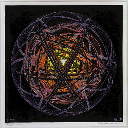
The geometry bugged me for a while until I finally figured it out and sketched it up in OpenSCAD:

Animated:
Here’s a cleaned up version of the OpenSCAD script to generate it – it’s surprisingly simple:
module torus_strip(r, width, thickness) {
    rotate_extrude(convexity = 10)
        translate([r, 0, 0])
        square([thickness,width], center=true);
}

module the_ring(r) {
    torus_strip(r, 2, 0.5);
}

$fn = 256;

rotate(180*$t)
for (r=[50,40,30,20]) color([1-r/50+0.5,1-r/50+0.1,r/50+0.1]) {

    rotate([ 0, 0, 0]) the_ring(r);
    rotate([90, 0, 0]) the_ring(r);
    rotate([ 0,90, 0]) the_ring(r);

    for (tt=[-60,-120]) rotate([0, tt, 0])
        for (t=[0:45:360-1]) rotate([ t, 0, 0])
            the_ring(r);

}
It took a while to figure out the geometry, but I finally got it when I saw there were three rings that were simply orthogonal, plus two arrays of 8 rings that intersected at the octagons. That’s how I modeled it above.
I also played with the animation stuff and got this:

Which I think is also neat.
That’s all.
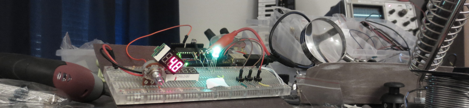
Magnet sensor (A3144’s) + magnets + spinny disc = tachometer.
Here’s the quick and dirty code I used — it’s good enough for a demo.
EDIT: Ha, I found a video of someone else doing the same thing, but with roughly a BILLION more steps. People gotta learn how to be lazy.
 In this article I’ll show a simple 3D design for a servo mount to control a light switch for about $3, plus some electronics to drive it with a neat little interface. This article explains how I used it to regulate my air conditioner, but the basic bracket allows control of any U.S. standard wall switch.
I just moved into a new office and there’s a window-mounted air conditioner. There’s a remote control to set the target temperature, but the unit isn’t smart enough to turn off at night. Instead, there’s a physical wall switch so you can turn it off with your actual physical hands, like a barbarian.

I’m not going to put up with a hot office in the morning, nor will I let the unit blow cold air all night and weekend when nobody’s around. Instead, I will Build Some Crap.
Details after the break. Continue reading AC power control without touching AC power
![2015-11-01 02.41.35.mp4_snapshot_00.03_[2015.11.03_16.22.52] - labeled](http://discspace.org/wp-content/uploads/2015/11/2015-11-01-02.41.35.mp4_snapshot_00.03_2015.11.03_16.22.52-labeled.jpg)
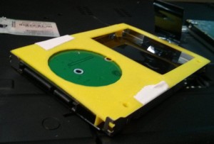
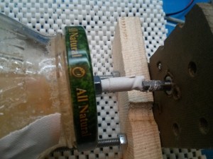
Step 1: Make a rock tumbler out of some threaded rods, bearings, a motor, and a spaghetti jar:
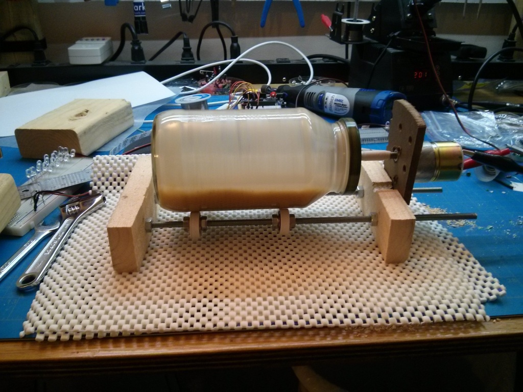
Step 2: Get sand. If you don’t live in a beach/desert, you can probably get some for free from a landscaping supply place. (They charge per ton, so when you ask for a cup, they will think you are a crazy person and just give it to you.)
Step 3: Chuck the LEDs and sand into the thing and run it overnight.
That’s all.
Here’s what not to do:
Video:
NOTE: Everything involved in this post is available for download here.
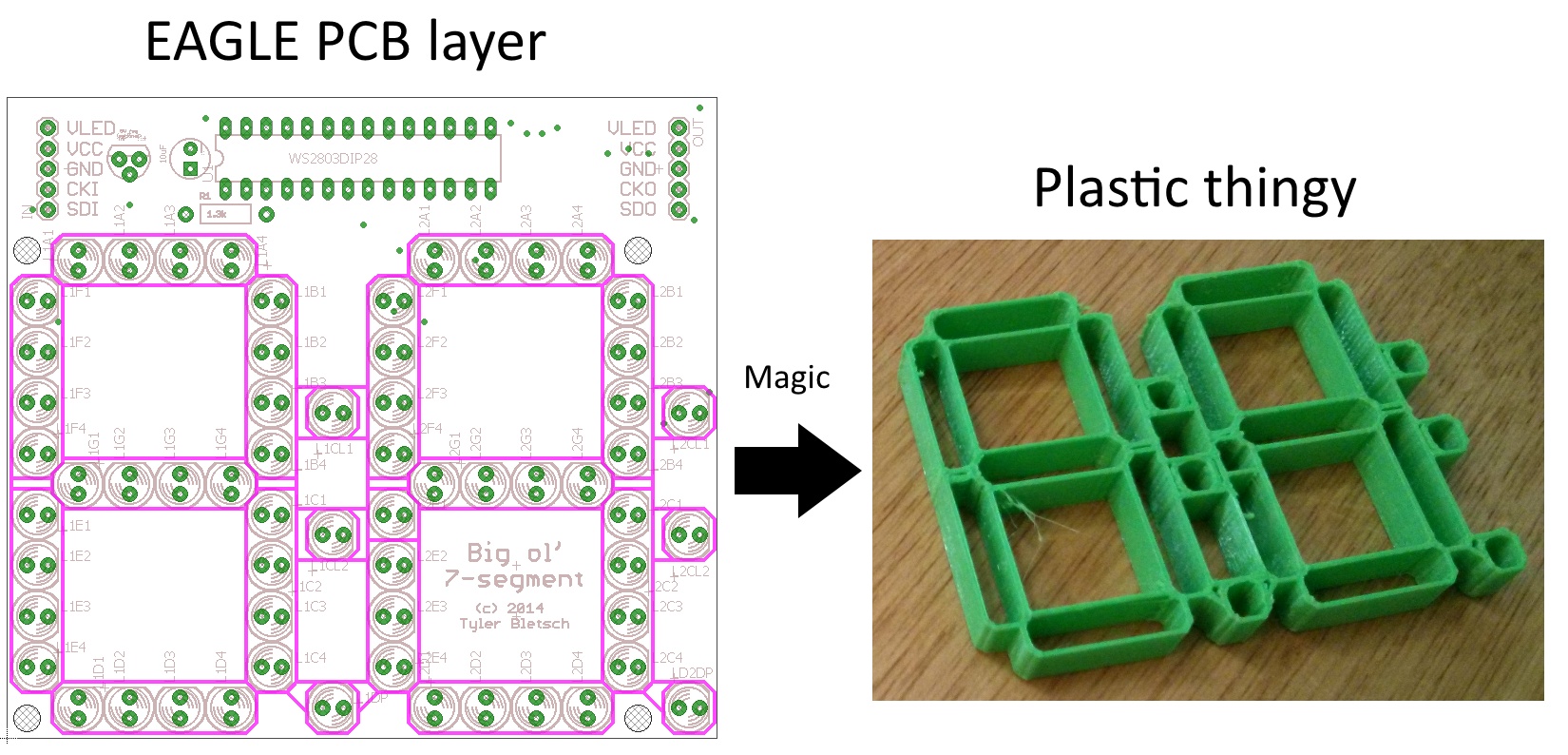
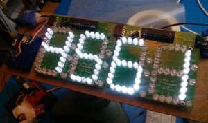 I while back, I made this PCB that acts as a big daisy-chainable two-digit 7-segment display using the WS2803D and discrete LEDs. The pic to the right is a shot of the first use of these PCBs: a big sign that says “4561”.
It works great, interfaces easily with AVR/Arduinos, and is cheap to build.
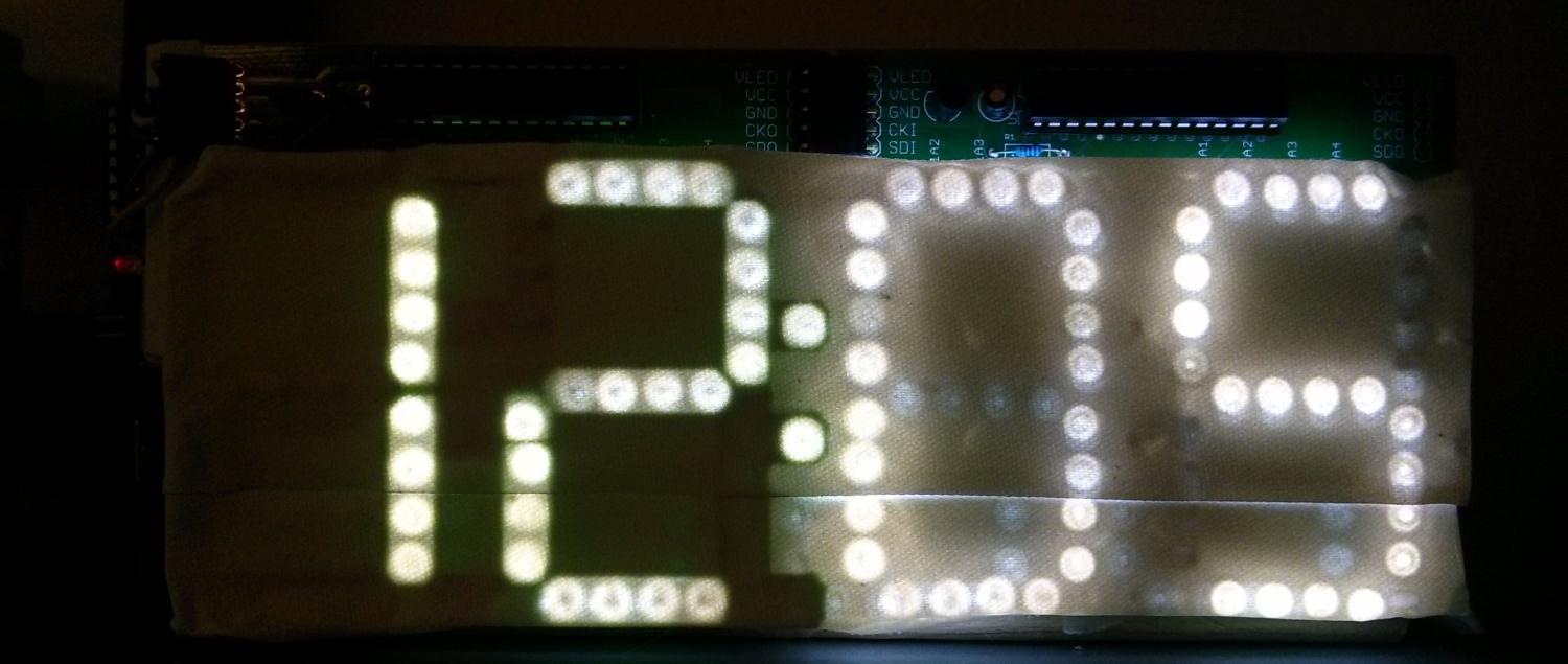
One thing that’s not great about it is the amount of light leakage from the LEDs — if you put some kind of light diffuser in front of it, you see all kinds of reflected and refracted bits of light. Here’s a shot of a clock I made out of these boards with white gaffer tape as a diffuser:
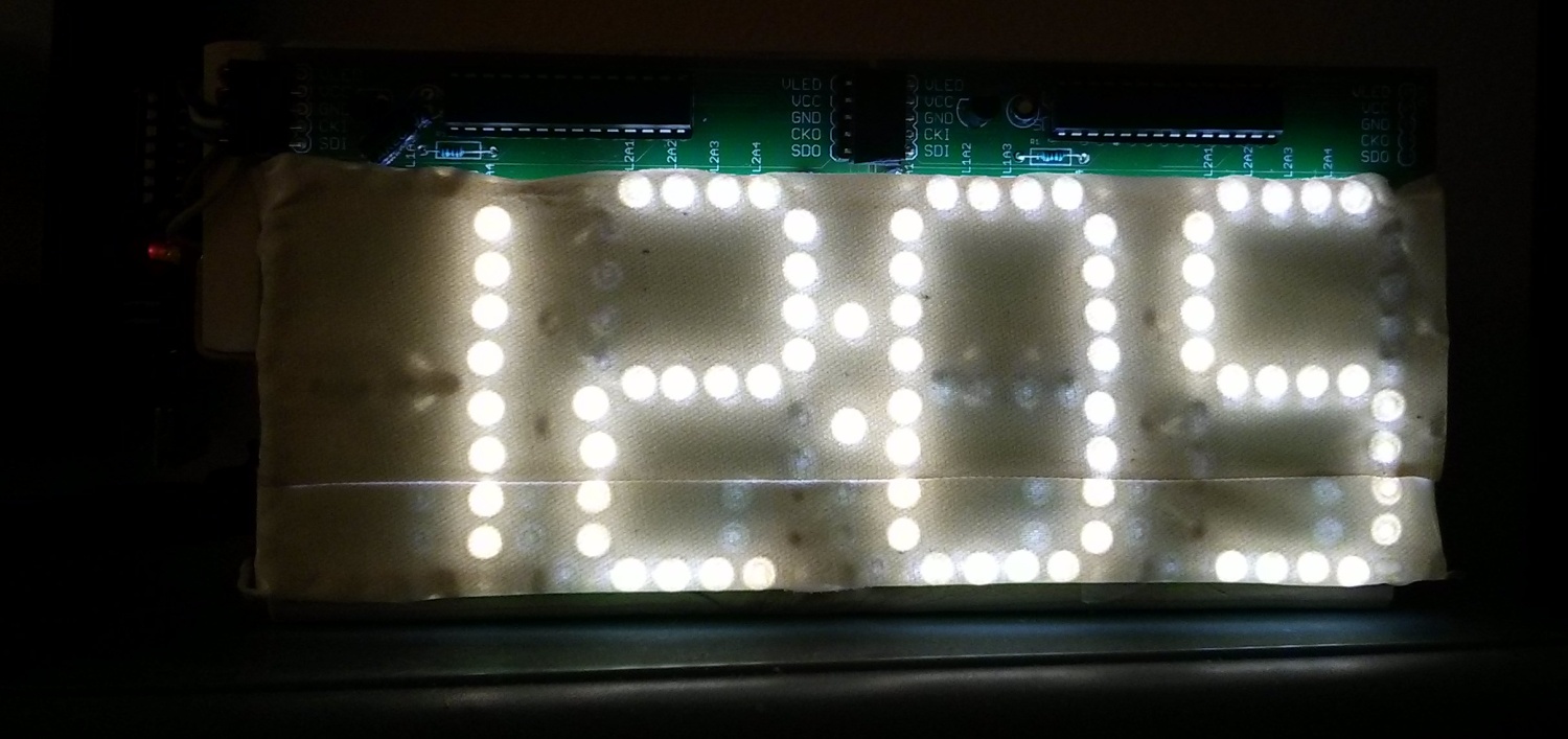
Look at all those random patterns of light…it’s shameful.
Today I figured out a simple way to 3D print a light mask for this board using design elements straight out of EAGLE! Here are the high-level steps:
Here’s a shot of the light mask applied to the left two digits of the clock:
Full directions after the break. Continue reading Generating 3D-printable pieces directly from EAGLE PCB designs
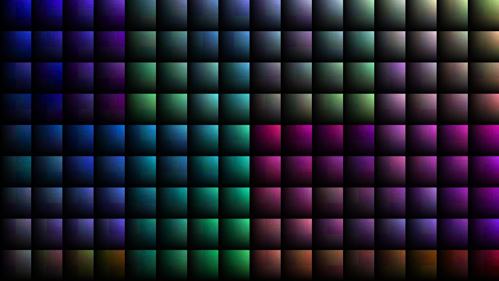
I don’t feel like writing a big post explaining all of it, so the summary is that I spent a few hours playing with colorspaces, Hilbert curves, and image generation, and produced some stuff that looks kind of neat. I’ve posted everything in one big wad, and you’re welcome to poke at this ugly undocumented code if you like. I also posted prior Python art scraps.
All the images in this post are shrunken down — the full size loss-less PNGs are on the github with the code. This is the kind of thing it kicks out:

Basically, I walk a 3D color space via a 3D Hilbert curve, mapping it to a 1D scalar. I then walk that 1D scalar on a 2D Hilbert curve, rendering each color in place in an image. Here’s an example of a 1D sequence of colors walked:

From there, I fiddled with the various outputs in Paint.NET to make pretty pictures, e.g.:
 (Original here) I was able to render the above one at a ridiculous resolution (8192×4608), so it looks awesome spanning four monitors.
Others:

Check out the github dump for more.
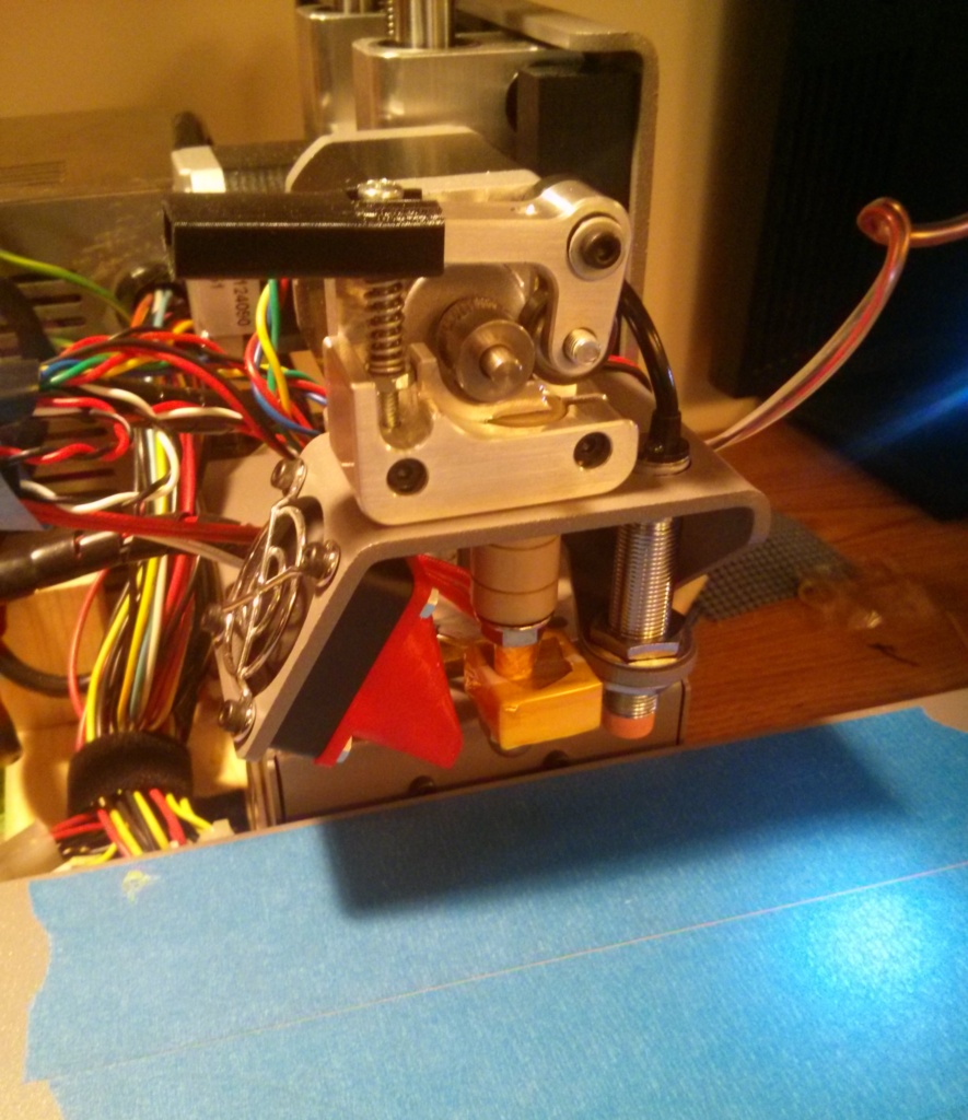
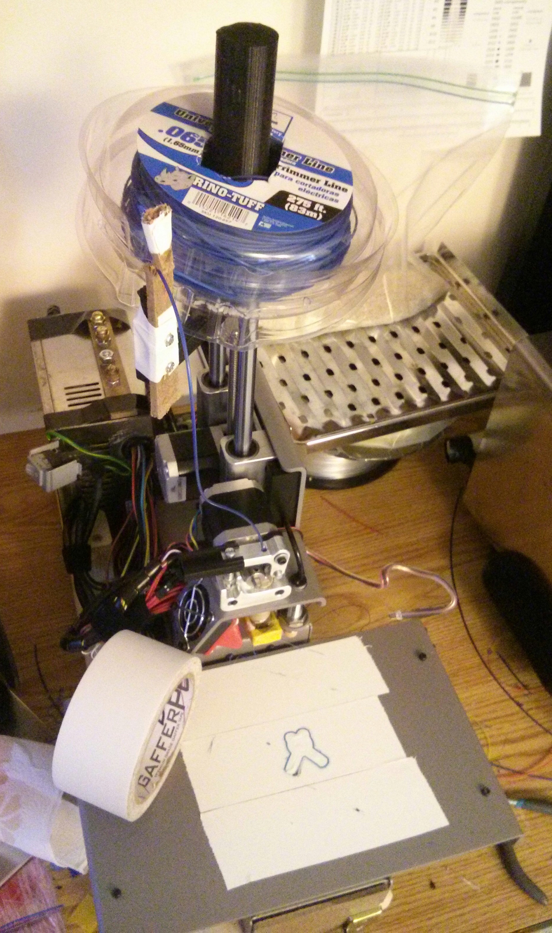 People have been experimenting with Nylon trimmer line for a while, and I wanted to give it a shot, since nylon is tougher, more flexible, smoother for moving parts, and can handle higher temperatures. I found a few small tips which I believe are novel, specifically that (1) gaffers tape makes a fantastic print surface while preserving inductive level sensing, (2) minimum print time per layer is the key to getting good prints with Nylon at high temperatures & speeds, and (3) dickbutt is the best test model in the world.
Summary of findings for the impatient:
More details after the break.
Continue reading Using Nylon trimmer line with a PrintrBot and Gaffer’s Tape
I really like my PrintrBot. It’s compact, reliable, and straightforward to build.
 Unfortunately, when I started getting ambitious with experimentation, I got into trouble. Basically, I started experimenting with things. First, it was printing with Nylon trimmer line. I was too impatient to dry the line as instructed, so it clogged everything up like crazy. That left me without a nozzle until I could figure out a way to clean it, and while I eventually did, it led me to wanting backup nozzles. That’s when I started to discover how odd-ball the PrintrBot is compared with most 3D printers. It doesn’t take the nozzles that 95% of other printers do…instead of an M6-threaded male nozzle, it takes an U.S. 1/4″-20 female nozzle (see here for a comparison).
This made me look into fabricating my own nozzles, because there aren’t third-party ones out there, and hell if I’m going to pay PrintrBot $8 a pop plus shipping for a bit of machined brass.
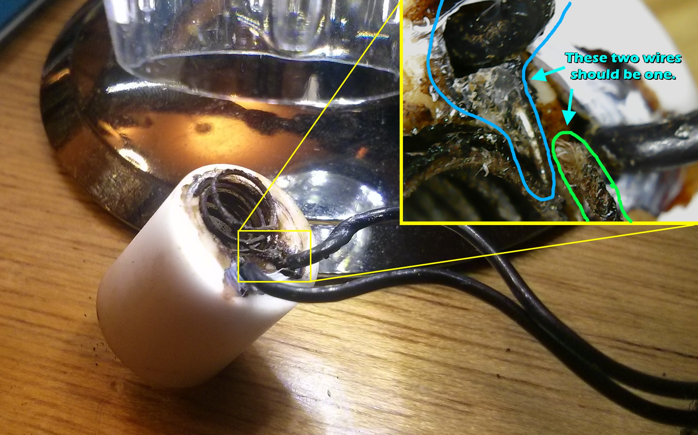
Unfortunately, the PrintrBot’s hot end assembly is also fairly proprietary, and also has an annoying flaw — the heater wires aren’t well protected, so if you tighten too much when swapping nozzles, they’ll break. This is double bad, because the hot end gets hot enough to melt normal solder, so you can’t even repair the break. Picture:
 So it looked like I’d need a new heating element. Unfortunately, this is another area where PrintrBot is very far from standard — nobody else uses this kind of heating element, and the PrintrBot store wants $59 for a replacement. Meanwhile, the standard (as defined by cheap imports from China) is a small aluminum block with a heater cartridge and thermistor mounted inside of it (see right) that costs next to nothing. These hot ends are fully metric, with M6 threading for both the nozzle and shaft.
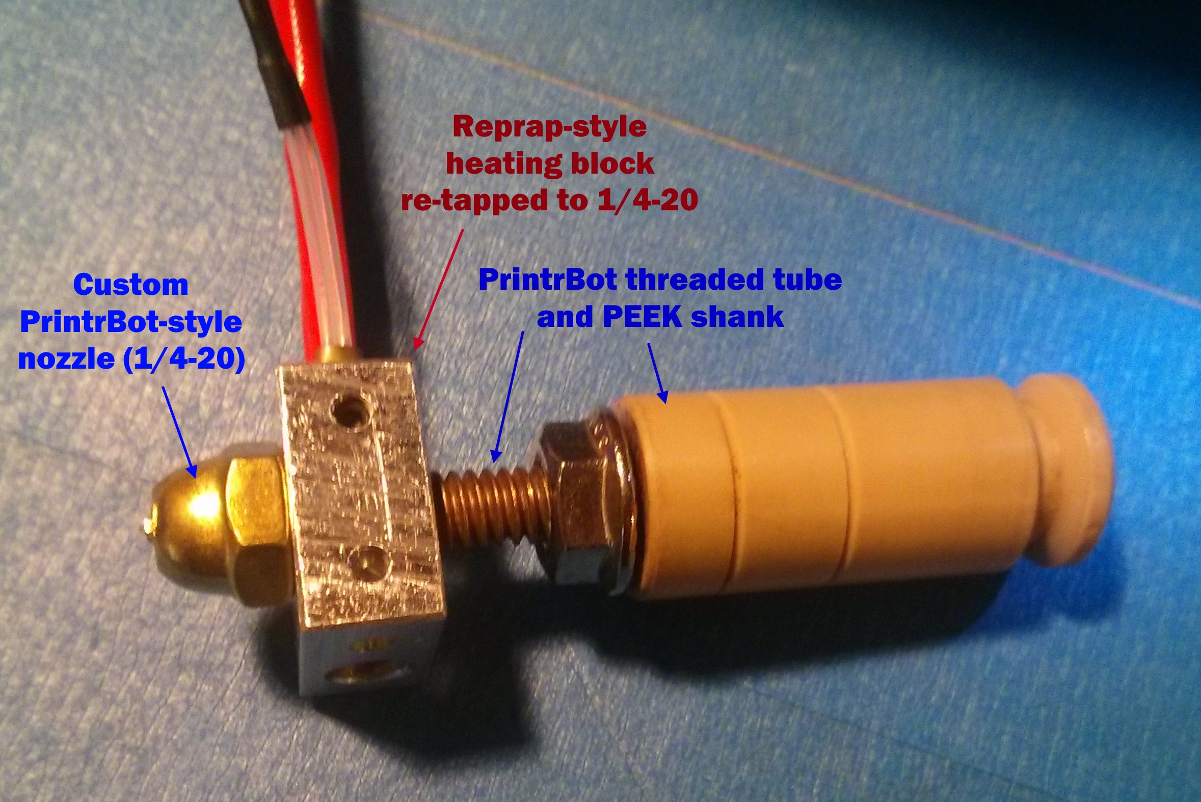
I happened to have one of these, so I had an Apollo-13-air-scrubber style problem: how do I get the Reprap-style M6-threaded heating element to graft onto the U.S. sized PrintrBot nozzle assembly?
I tried several combinations to no avail, until I realized that I could re-tap the M6 hole in the Reprap-style heating block to 1/4-20. Then I could thread the entire PrintrBot hot end tube through it, reassemble it per usual, and be back in business! So that’s what I did…with just a minute with a 1/4-20 tap and a bench vice, I converted the heating block to be PrintrBot compatible:
To keep it tight, I used teflon table on the nozzle, and tightened the heating block against the nozzle itself. This has a bonus effect of heating the nozzle most effectively.
To hook up the connections, I just attached Dupont pins to the thermistor (female) and heater cartridge (male). The pins hook up fine, but I didn’t have the fancy PrintrBot-type connector housings. No matter – a bit of tape keeps them secured.
In the end, it worked! The only issue I had was that it had trouble staying at temperature — the heating block leaks heat like crazy, especially when the fan is on. To fix this, I wrapped it in a bit of PTFE threadlock tape, then a layer of Kapton tape to hold it:
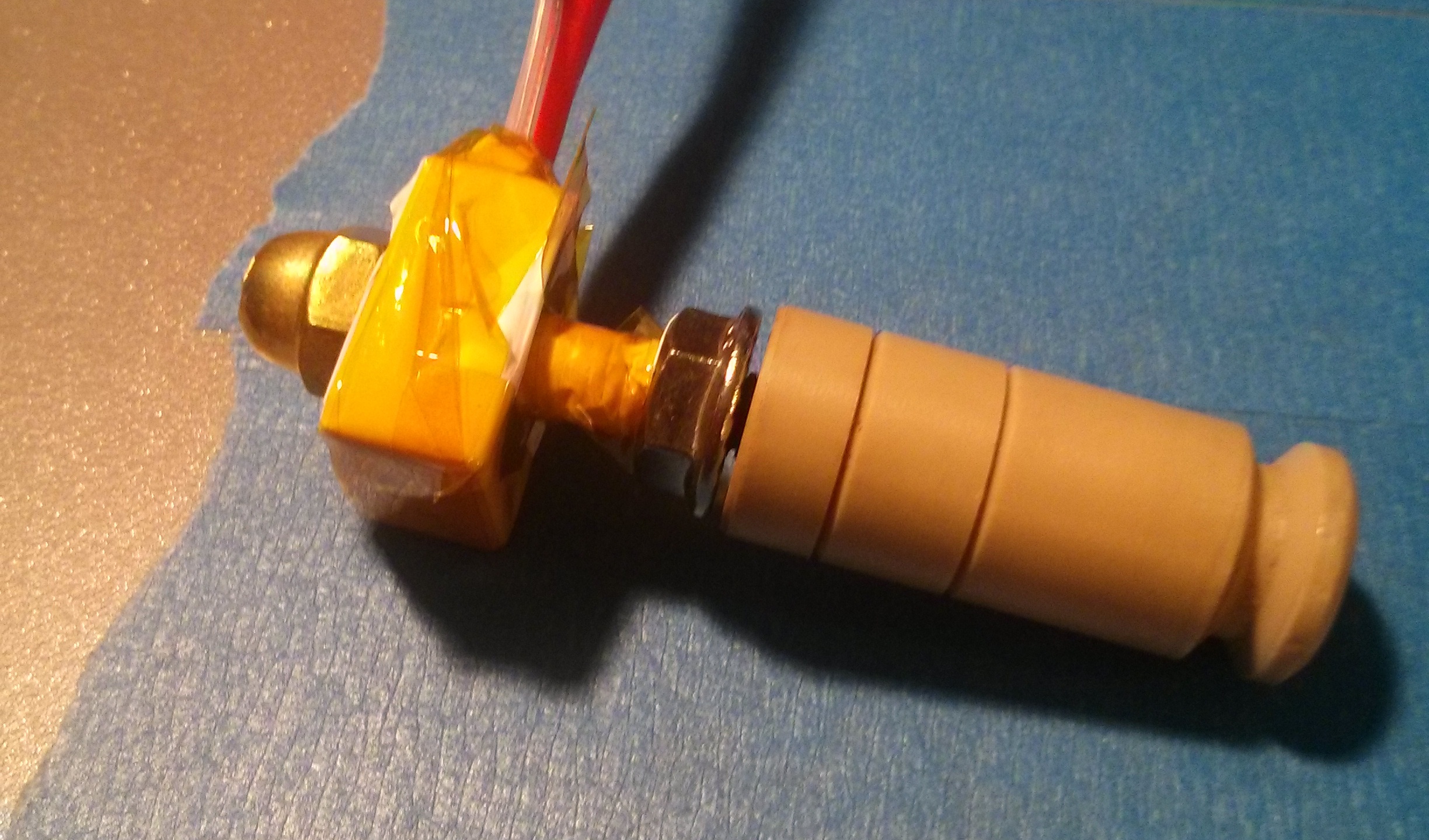 With this done, I remounted it, recalibrated a bit, and was kicking off prints!
 Side note: I also found an easier way to fabricate nozzles than the link I provided earlier. I just got some brass cap nuts, as the original directions prescribe, but instead of building a makeshift lathe, I just started by drilling the hole, then “milled” away excess material from around the outside of the hole freehanding with a dremel cutting disc. Knocked out a 0.5mm nozzle in about 5 minutes.