This is a guest post from my friend Rebecca on her adventures building her own Ax Clock. -Tyler

This blog post came about because I saw Tyler’s Ax Clock post and wanted one for myself. He wrote a nice blog post about it, but I didn’t know enough to make it myself so I asked him to help me. As we were making the clock, Tyler asked me if I would like to make a guest post on his blog. I was not sure if this was a good idea because a) Tyler has already made a post about this same project and b) I know basically nothing about electronics or programming. This did not stop me from immediately agreeing to do it.
Full story after the break.
Tyler originally made his clock because he found some circuit boards super cheap at a surplus store called Ax Man. I have never been to Ax Man, but I have heard a lot about it and I will share my knowledge with you. Ax Man:
- Is in Minnesota
- Sells random industrial parts
- Has creepy robots
I’m not sure, but I think Ax Man is a cross between a Chuck E. Cheese and some sort of wretched hive of scum and villainy.
Tyler made the circuits on the original Ax Clock using a breadboard, but has since discovered that he can make custom circuit boards and order them really cheap online. The company that we ordered the custom circuit boards from is called Osh Park. If you want to know more about how custom circuit boards are made, I suggest you ask Tyler because I am fairly certain he could talk for a week straight about nothing else, and I have pretty much already given all the knowledge I have.
Now, Tyler already made a circuit board to replace the breadboard for a secondary Ax Clock that he made so I didn’t have much to do with the creation of that. He even did all the necessary soldering so I didn’t have to worry about that either. However, I wanted my clock to tell the temperature. Because the circuit board was not equipped to do so, we had to figure out what we would need in order to create a board that worked.
We started by making a circuit on a breadboard. Now, I don’t have any pictures of this because it was about a month ago. I also don’t remember the steps taken or anything like that. Instead, I will be giving you some tools so you can use your imagination to visualize the event.
Here is a picture of a breadboard:

And here is a picture of me:

Now, imagine me trying to poke tiny wires into the tiny holes of the breadboard and swearing a lot. If you can imagine that, you pretty much have the gist of how it went.
After we finished making the breadboard circuit, Tyler took care of the programming. This is not turning out to be a very informative blog post, but I really had very little to do with this step. I know a little bit about programming, but not enough to tell you anything about this particular program.
The next step was to design a special circuit board for the temperature sensor. It had never even occurred to me that I might be able to design a circuit board. I actually found this step pretty fun. It was like a puzzle; you have to find a way to put everything that you need in a tiny space and then figure out where everything connects without paths crossing and that sort of thing. Tyler had to help me a lot because I didn’t know how to use the program needed to design the board and I also wasn’t really sure what everything was anyway, but I think I did a good job. Here is a picture with the important parts labeled:
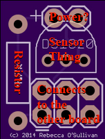
As you can see, I don’t remember what everything was. Tyler had to help me a lot and I was a little embarrassed to admit I was confused. By my memory, the conversation went something like this:
Tyler: Okay. Now you need to add the florpnot to connect the schnozzle-bean.
Rebecca: Uhhh…
Tyler: Right there. Click the garginhoofer and the program will findle the fleebop.
Rebecca: Oh yeah, I understand now. The fleebop works with the power…?
Tyler: NO! The fleepbop flinders the schnorgenzoof!
You get the idea.
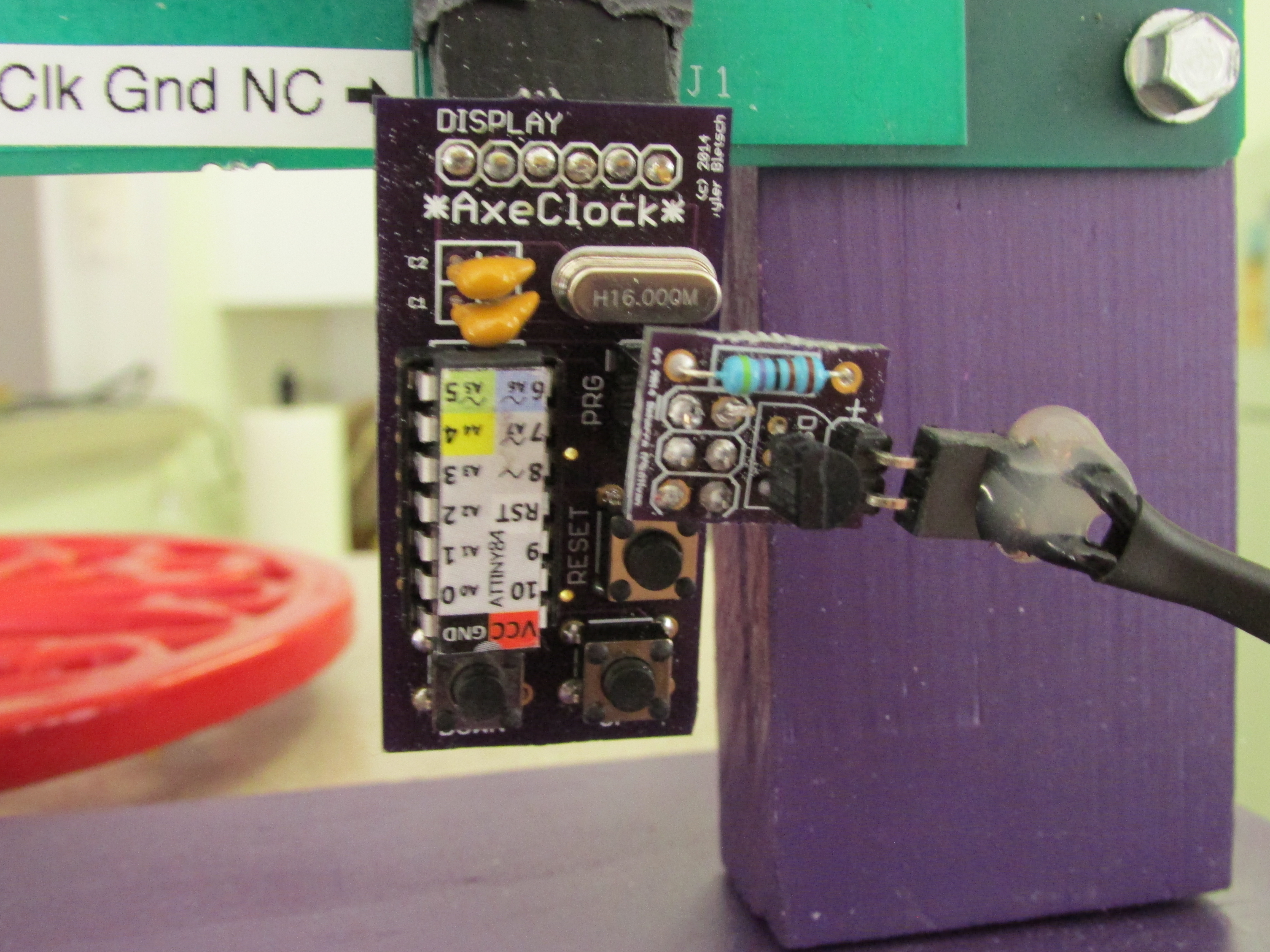
As a side note, the part I was most excited about was getting my name screen-printed on the board. Here is a picture of the actual chip so you can see how big my name was. It’s at the very bottom.

You pretty much can’t read it. Oh well.
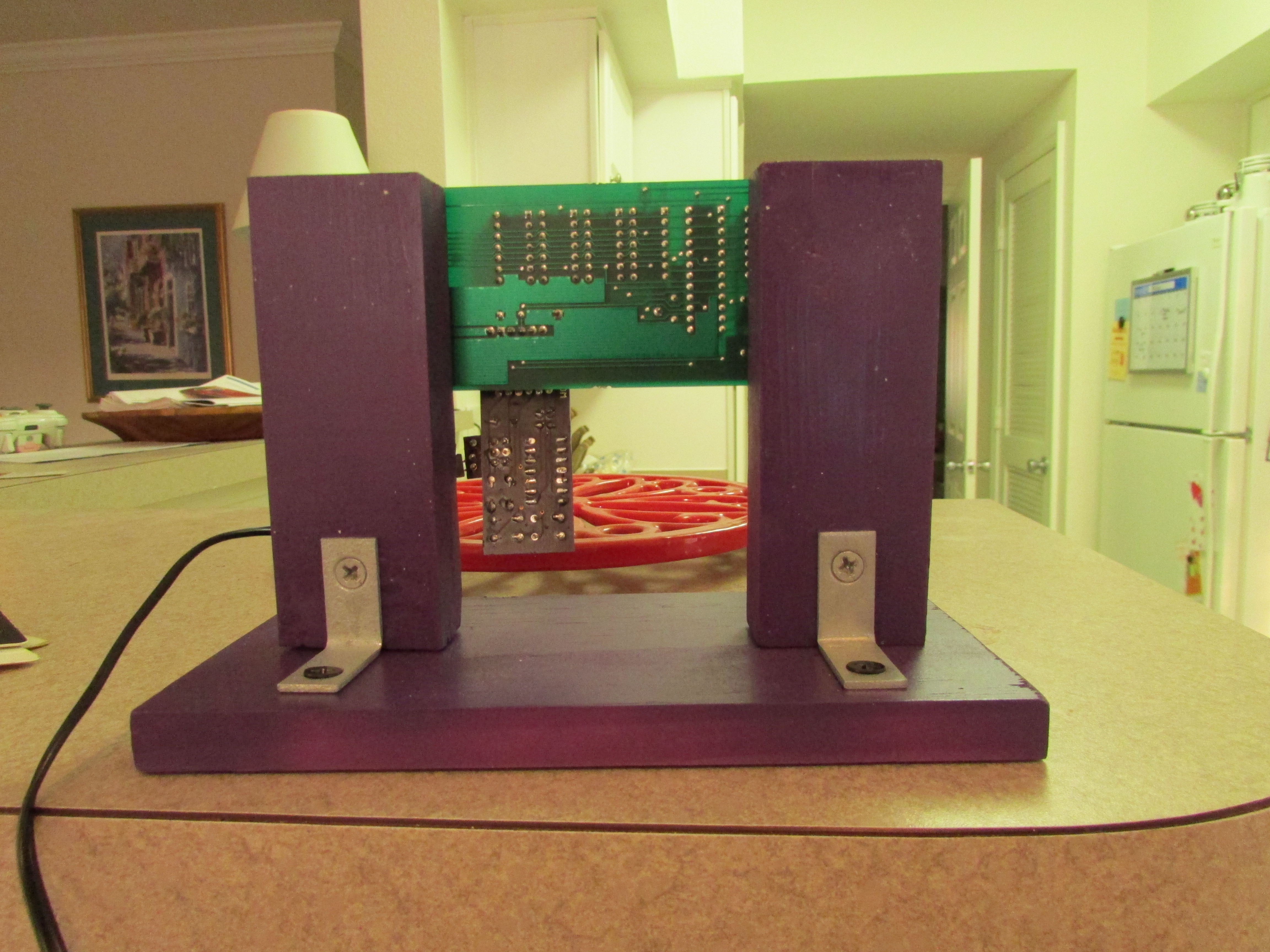
The next thing I had to tackle was building something to hold the circuit boards and make it look more like something I would want to display. I did this part entirely by myself and I am particularly proud of it. A year ago, I had pretty much no experience using tools of any kind, but my husband and I (along with Tyler) are mentors for a FIRST Robotics team. The team has given me the opportunity to actually gain some mechanical knowledge. If you want to know the level of my initial ignorance, Tyler had to show me how to use a drill approximately 6 months ago. This project wasn’t particularly taxing, but it’s still nice to be able to accomplish something like this without a safety net. It’s basically just 3 pieces of wood and some wood screws. Truth be told, the hardest part was standing in the paint aisle at the hardware store trying to decide what the “right” shade of purple was. Regardless, I am still very proud of myself. Here is a picture of the back so you can see how it is put together.
After the chip I designed came in, it was time to put everything together and make a working clock. This mostly involved soldering. My father taught me to solder when I was 11 or 12, but we were repairing band instruments and using a propane torch instead of a soldering iron. It turns out that the concepts pretty much carry over. You heat something up, you melt metal onto it, and things stick together. I found a soldering iron much less intimidating than a torch because… you know… fire. Even so, the experience did inspire an excessive amount of swearing. You can see here the chip with all the components soldered on. I especially like the power cord because it’s insulated with hot glue.
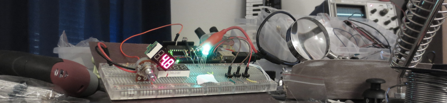
Here is a picture of the finished clock. It is a nice little addition to my desk area.
There you have it. It makes me smile every time I glance at it while I’m working. You may not be able to re-create this based on the information provided here, but I hope you enjoyed reading anyway. If you didn’t, here is a picture I made of Tyler with the Ghostbusters.