The Nickelphone

(Wow, just found out that this made Hack A Day, cool!)

I just finished the Nickelphone!  It’s a coin-based music keyboard. 15 nickels and 10 pennies act as touch sensors on a traditional 25-key piano-style layout. It can emit simple square wave tones through an onboard piezo buzzer, but its primary use is as a MIDI keyboard, so it can drive a full synthesizer (like FL Studio on PC). It’s based on an ATmega644 microcontroller, chosen because each key needs its own pin, and this chip has 32 data pins (8 of them analog inputs).  (Also, it happens to be the chip I got for free in when I placed my Atmel free sample order.)  It uses the “no extra parts” capacitive sensing method developed by Mario Becker and others.  For the MIDI output, I used the “last darned MIDI interface I’ll ever build” by Stephen Hobley (just the output part, which just uses one resistor).  The software is written in Arduino, with the “core” for the ATmega644 chip being adapted from the Sanguino project.  The Nickelphone was inspired by Linus Åkesson’s Chipophone and its follow-on, the bitbuf, both of which are totally awesome.

Read on for details…

Continue reading The Nickelphone

Nickelphone update

Here’s an update to the Nickelphone (previous post here). It’s still made out of 15 nickels and 10 pennies acting as touch sensors on a traditional 25-key piano-style layout. It now has MIDI output and can detect any number of simultaneous key presses, so it works great with a full synthesizer (like FL Studio)!

I still need to do a full write up, and make it a little more well-built.


The Nickelphone – work in progress

Here’s a work in progress video of my home-made musical instrument, the Nickelphone.


It’s a coin-based music keyboard.  15 nickels and 10 pennies act as touch sensors on a traditional 25-key piano-style layout.  It currently emits one tone at a time through a little piezo buzzer, but it will eventually emit MIDI signals so it can drive a full synthesizer (like FL Studio).  Based on an ATmega644 microcontroller and coded in Arduino with the CapacitiveSensor library for touch sensing.

I’ll do a full write-up here when it’s done.

How to make cheap wooden 6-sided dice

2013-09-29 20.36.59b

I’ve been thinking to switching to a different dice system for my role playing system, FudgediceMEGAPOMPS.  I’m not sure yet, but I think I want to try using Fudge dice, which have two plus signs, two minus signs, and two blank sides, as shown in the pic to the right.

The problem is that while these aren’t very expensive for a set of four (about $5 on ebay), I’m not about to ask everyone I play with to buy a set of weird dice just to experiment.  But they’re simple enough, so I thought I’d make some.

All I needed was a bunch of wooden cubes — about 5/8″ to a side (15mm).  I found an ebay sale for 36 of them for $3 shipped.  These cubes won’t have the precision of real plastic dice, but they’re cheap in bulk — much cheaper than even blank plastic dice.  I had to throw 5 of the 36 out for being uneven or chipped, but who cares.

To mark them, I just used my soldering iron.  I put in a medium-sized chisel tip, but most any would work.  I held them in place with a needle-nose, and slid the broad side of the iron over the face of the cube to burn in a + on two opposing sides, and a − on two others.  It was easiest to do this with the grain of the wood.  On some of them, I stabbed a dot into the blank side just for effect.

2013-09-29 20.38.18b

When they were done, the burned wood had a sticky texture, so I briefly washed each face with a wet rag, and they were fine.

Also, I had a few extra, so I made some standard numbered d6’s by just stabbing in the right number of pips on each side:

2013-09-29 20.37.41b

Boom, $3 and an hour of time and I have some neat homemade Fudge dice, plus a few regular d6’s to throw in the bag.

2013-09-29 20.36.37b

Draw anything on an oscilloscope

2013-09-21 10.15.01b

I have an old analog oscilloscope I got from university surplus, and it’s been more than enough for all the work I’ve done so far.

One thing I’ve wanted to do for a while was draw arbitrary stuff on it using X/Y mode, recreating the vector graphics systems of the past, especially stuff like the seminal Tennis for Two.  Unfortunately, a plain Arduino can’t output true analog signals–the analogWrite function just sets pulse-width modulation (PWM) so the pin is up x% of the time rather than truly being x% of the voltage.  So I needed a digital-to-analog converter (DAC).

I was originally going to build a R-2R DAC out of resistors, but that eats a ton of pins, so I wouldn’t be able to scale down to a smaller controller later if I wanted.

Instead, I decided on getting a dedicated serial DAC, which is an IC that receives the voltage level via serial digital communication, then outputs it.  Originally I tried to get a super-cheap audio DAC, the TDA1543, but the protocol for that is weird, and I got a non-standard “japanese interface” variant, and also I may have fried it.  Anyway, it didn’t work, so I got the much more standard MCP4802.

The MCP4802 is from the MCP48xx line (datasheet), with the model number indicating it has 8 bits of resolution and two independent channels.  It communicates over plain SPI, a well known standard with hardware support on Arduino.  I found a ready-made library for it here. (I had to fix one thing in it — it didn’t include SPI.h in its own header file. I also renamed CHANNEL_A/B to CH_A/B for brevity.)

I wired it as described here, and it worked perfectly.  With this, I hooked up the X and Y lines to the two outputs of the DAC, and set about drawing some stuff.  After getting it to draw a circle (x=cos(theta), y=sin(theta), scale output to 0..4095), I decided to draw some arbitrary stuff.

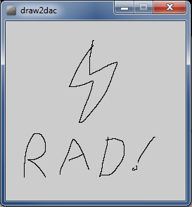
To encode the art, I wrote a small Processing app to let me mouse-draw some stuff, with the coordinates being saved to a file in CSV format.  Code:

PrintWriter output;

void setup()
{
  size(256,256);
  output = createWriter("positions.txt");
}

// x0=-1 means "the next click is the start of a new line segment"
int x0=-1,y0=-1;
int x,y;

void draw() {}

void mouseDragged() {
  x = mouseX;
  y = mouseY;
  output.println(String.format("%d,%d",x,(256-y)));
  output.flush();
  if (x0>=0) {
    line(x0,y0,x,y);
  }
  x0=x;
  y0=y;
}

void mouseReleased() {
  x0=-1;
}

So now I can draw stuff:

rad

I wrote a small Python app to convert the CSV list of coordinates to array declarations for Arduino. (I could have done this formatting in Processing directly, but that would have involved arrays and a save function, and I’m not very familiar with Processing yet, so this was faster.)  This code also drops every other coordinate to improve the refresh rate.

import fileinput

X=[]
Y=[]

every_n = 2 # we throw away every other pixel to improve the refresh rate

i=0
for line in fileinput.input():
	i += 1
	if i%every_n != 0: continue
	x,y = line.strip().split(",")
	X.append(x)
	Y.append(y)

print "byte X[] = {%s};" % ','.join(X)
print "byte Y[] = {%s};" % ','.join(Y)

I run it with:

  $ python pos2code.py positions.txt > rad.txt

I then dropped those two lines into the top of my Arduino program:

// MCPDAC relies on SPI.
#include
#include
#include

int i=0;

byte X[] = {...INSERT VALUES HERE...};
byte Y[] = {...INSERT VALUES HERE...};

void setup() {
  MCPDAC.begin(10,9); // CS pin, LDAC pin (latter only needded for x/y sync)

  MCPDAC.setGain(CH_A,HIGH); // Set the gain to "HIGH" mode - 0 to 4096mV.
  MCPDAC.setGain(CH_B,HIGH); // Set the gain to "HIGH" mode - 0 to 4096mV.

  MCPDAC.shutdown(CH_A,false);
  MCPDAC.shutdown(CH_B,false);
}

void loop() {
  int x,y;

  x = X[i]*16; // *16 to go from 0..255 to 0..4095
  y = Y[i]*16;

  MCPDAC.setVoltage(CH_A,x&0x0fff);
  MCPDAC.setVoltage(CH_B,y&0x0fff);
  MCPDAC.update(); // this toggles LDAC, actually changing the outputs -- you can omit this if not using the LDAC pin (leaving it grounded)

  i++;
  if (i>=sizeof(X)) i=0; // wrap around the array

}

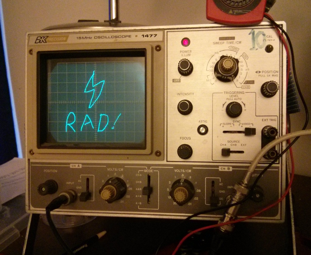
The program cycles through the values, sending them to the MCP4802, thus driving the oscilloscope, which was set to XY mode.  Now I can play with the code above to start trying out some effects, like this “crawling ant” pattern:
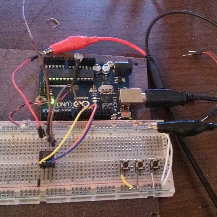
My setup:

2013-09-21 09.43.28c

Cache up internet radio for later *skippable* playback

If there’s an internet radio station you like, you might want to listen to it on the move, even when you don’t have internet.  It’s fairly trivial to slurp the MP3 stream with a tool like wget, but then you end up with a 4GB single file.  It’ll play fine, but when a crappy song comes on, it would be nice to skip ahead without having to hold down the “forward” button for a while. Worse, many MP3 players don’t keep track of position in a song, so when you start back up, you’ll be at the start of the stream again.

What I do is slurp the MP3 stream, but divide it into fixed chunks, like 5MB.  You can tell how much runtime per chunk based on the bitrate.  A 128kbps stream means there are 128*1024 bits per second, or about 0.983 megabytes/minute.  So 5MB is roughly 5 minutes.

This means I have a directory with a few hundred MP3 files to be played in sequence.  If you have gapless playback, you don’t even notice the track changes. If you’re listening to a lousy song, you can skip 5 minutes into the future just by pressing next track.  Even lousy MP3 players keep track of which song you were on, so your radio picks up where it left off, and even if you lose your place, it’s easier to find your way back, since you can just skip five minutes at a time until you start hearing new content.

To do this chunk download approach, I use this old perl script I wrote a few years ago. It’s a little ugly…if I were to write it today, it would probably be 10 lines of Python, but it works well enough, even on Windows (provided you have perl and wget).

#!/usr/bin/perl

use strict;

if (!@ARGV) {
	die < [basename] [size]
EOL
}

my $url = $ARGV[0];
my $basename = $ARGV[1] || "save";
my $chunksize = $ARGV[2] || 5*1024*1024;
my $blocksize = 4096;

my $chunkleft = $chunksize;

open STREAM, "wget -O- $url |" or die;
my $n=1;
while (1) {
	my $buf;
	my $filename = sprintf("%s-%03d.mp3",$basename,$n);
	open OUT, ">$filename" or die "$filename: $!\n";
	while ($chunkleft > 0) {
		my $r = read(STREAM, $buf, $blocksize);
		if ($r == 0) { die "EOF, exiting.\n"; } 
		elsif ($r<0) { die "stream: $!\n"; }

		$chunkleft -= $r;
		print OUT $buf;
	}
	close OUT;
	$chunkleft = $chunksize;
	print "\nFinished writing $filename.\n";

	$n++;
}

How to trace circuit boards easily

Circuit boards, even small ones, look crazy complicated. But they really aren’t — they’re just efficiently packed. Most circuit boards have just two “layers” of copper traces running around: top and bottom. Something sophisticated like a computer motherboard can have more copper sandwiched in the middle, but most of the things a hobbyist would want to trace are just have a top and bottom.

What can make tracing complicated is that the two sides work together, with a single connection flipping between top and bottom multiple times.  But we can use a camera and an image editor like Paint.NET, Photoshop (the CS2 version is free now), or GIMP to make it easy.

As an example, let’s trace this USB device.  It’s an off-brand programmer for AVR chips that had no documentation and didn’t work in a standard way like similar products, so I had to figure to figure out how it was wired up.

I started by taking good, high-resolution pictures of each side, trying to keep the camera a fixed distance from the board on each side.  Using a document scanner didn’t work for this, because the board didn’t lie flat on the glass…you might be able to use a scanner for a flatter circuit board.

side1side2

We’re going to superimpose the bottom (simple) side over the top (complex) side in the image editor.  Take the picture of the simple side, copy it, and paste it as a new layer over the complex pic.  Set it to semi-transparent, flip it vertically, then use the layer transform or move tool to get it to line up exactly over the top side of the board.  Be sure to match up key landmarks, like vias (the little holes that connect top and bottom) and through-holes.

Once they match, turn the simple side opacity all the way back up, add a new empty layer, and paint all the traces you see in a high-contrast color (like red, for green boards).  When you’re done, you should be able to slide the opacity of the simple & red layers up and down and have it look like this:

anim2a

Now, turn off the simple layer, but keep the red trace layer.  Now you have a picture of the top of the board with all the bottom-side traces super-imposed:

together

Now you can add another layer and draw additional annotations that you need until you’ve discovered everything you need to know.

together-more

What I needed to know for this board was this: I was dumb to buy this $4 programmer just because it had a fancy case when the well-known good model was nine cents cheaper.  It’s a crappy nonstandard board nobody’s ever heard of, and though I could fix it by adapting custom firmware for it, I’m better off just throwing it in the bin and getting the good one (which I did).

But it was a good exercise in circuit tracing.

Hilbert curves are cool

Hilbert curves are cool.  They’re a form of fractal comprised entirely of 90 degree angles. It’s a way to make a single continuous line fill up any given space (2D, 3D, and beyond).

hilbert1

The background to this blog is a hilbert curve I rendered myself (code).  Above is a simpler version of the curve, blown up so you can see it, with the color of the line changing so you can see how it flows.

It has a some cool properties.  For example, if you subdivide the image width-wise and height-wise by a power of two, you get squares that also contain one contiguous part of the line.  It turns out this is important in computer simulations.  Because of how CPU caching works, it’s faster to read a bunch of bytes next to each other than ones far apart. So if you’re simulating weather patterns or particle physics or whatever, you have to map memory (which is one-dimensional) to 2D or 3D space.  If you use a hilbert curve to do that mapping, then when you divide the space up to work on it, each little square or block will live on a continuous piece of memory, and your program will run much faster.

Also, I just think they look cool.  I played with a few filters and came up with some cool images of the 2D hilbert curve:

hilbert-10-lavender-sin729x hilbert-10-rainbowedges-sin81x hilbert-10-rainbowedges-sin81x-quadmirror-rot45 hilbert-10-ice-sin81x hilbert-10-ice-sin9x hilbert-10-ice-sawtooth hilbert-10-fire-sin81x

Also, they work in 3D too.  I wanted to see this, so I wrote a program to build a 3D hilbert curve in Minecraft:

2011-01-17_22.34.05 2011-01-17_22.31.40 2011-01-17_22.31.332

The code to render these is here.  This code is two years old (Jan 2011), and it’s based on the pymclevel Python module, which may be dead or different by now.  Also, it outputs schematic files, which was a format you fed to a Minecraft map editor to plop the object into an existing world.

I also rendered another cool fractal, the Menger sponge:

2011-01-17_17.58.03 2011-01-17_17.58.30 2011-01-17_17.58.48 2011-01-17_17.59.40

Code to generate that is here.

How to hack the Sandbox game

The Sandbox” is a powder game recently ported to Android. It’s fun, but they try to get you to buy “mana” to unlock stuff that you need to use in the normal course of the game. Nope, not gonna do that.

We can hack the Android version to drop the price of elements to near-free.

To do this:

  1. Get the Sandbox APK by backing up the installed game (ES File Manager’s App Manager can do this)
  2. Transfer APK to PC
  3. Extract it as a ZIP file
  4. Edit assets/shop.plist to drop prices to 3 mana for each element
  5. Rezip the files
  6. Use the “testsign.jar” tool to sign the ZIP, thus making it an installable APK:

    java -jar testsign.jar hacked.zip ready-to-install.apk
  7. Uninstall the non-hacked game from your device
  8. Copy the hacked APK to your device
  9. Install the hacked APK.

All the elements should now cost just 3 mana, so head to the element store and unlock them all.

Getting around stability/sound issues

On my Nexus 7, the hacked version of the game didn’t have sound for some reason and I saw a few glitches.

To fix this, I just:

  1. unlocked all the elements,
  2. backed up the profile data (/sdcard/Android/data/com.pixowl.thesandbox.android),
  3. uninstalled the hacked APK,
  4. installed the normal APK, and
  5. restored the profile data.

After re-launching the game, the unlocked profile remains with sound restored.

Methods which didn’t work

There is a guide to hack the iPhone version by editing rewards.plist, a file which exists in the Android version too, but making the change suggested in that guide had no effect, which is why I hit the shop.plist instead. Perhaps they left that file as a red herring?

Also, you may be tempted to try to edit the player profile.dat directly to change your mana, and you can find the binary number to do it (offset 0x94), but the file is hashed with a 160-bit hash (probably SHA-1), and the hash is salted or something, because I couldn’t figure out how to re-sign it.