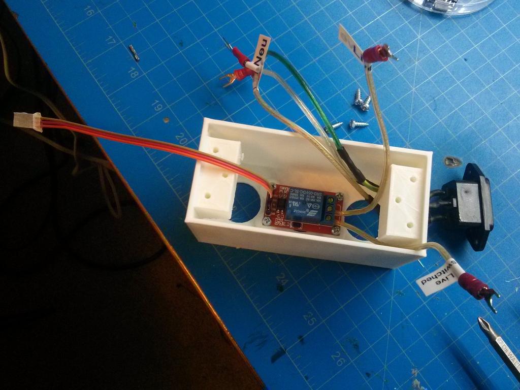
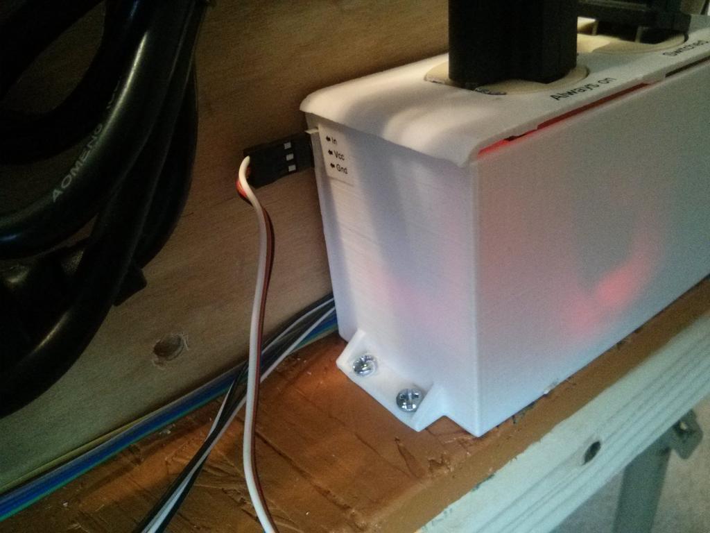
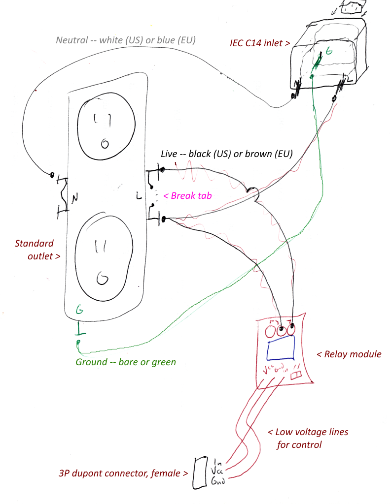
On Thingiverse I’ve posted a model and schematic for a relay-switched outlet box. This will let you switch an outlet on/off with an Arduino pin. That’s nothing new, but it’s a box that puts all the components together in a neat and safe package.
The intent of this model is provide a switched outlet for my Mostly Printed CNC machine (MPCNC). It’s designed to be narrow so it could mount on the side of the machine to (a) provide always-on power to the power supply and (b) provide switched power to the AC spindle motor. That said, this model is a general-purpose switched outlet, so you could use it for any automation of AC power you need.
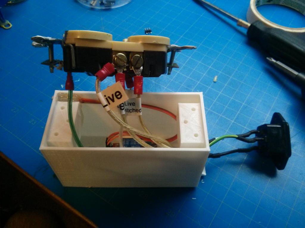
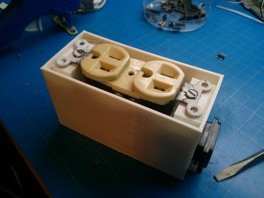
See photographs below for assembly directions. Notes:
Relay modules tend to vary in size — move the screw posts in the model if needed.
The relay control wire is just three double-female dupont jumper wires taped together and hot glued in place.
WARNING: This switches high voltage! If you are unsure how it works or how to build it, consult someone with electrical experience before proceeding! This isn’t hard to build, but it can kill you if you touch the guts when it’s live, and it can start a fire if wired wrong or with insufficient gauge wire (18AWG to probably not die, 14AWG to meet code).
This test model works as well in 2D as it does in 3D!
I tried a test run of the Optimal Fabrication Test Model (it’s dickbutt…we talked about this).
Results were…mixed. It started out strong by making key outline portions, so I left the room. I came back when I heard the spindle inexplicably struggling from downstairs. I come back to find the spindle has sunk all the way into the foam, and the nut that mounts the endmill to the tool has itself ground a sizable trench through the foam. Bits of foam are everywhere.
It turns out two separate failures happened. First, the Z coupler came loose…that’s my fault, as the plans called for nylon locknuts, but I couldn’t find any locally, so I used plain hex nuts, so the screws tightening it vibrated loose. Locknuts: ordered.
Second, there was a flaky connection on the X-axis, which is why it’s a vertical trench instead of a vaguely dickbutt-shaped trench. Apparently the wire I used doesn’t like to crimp well in Dupont connectors, so I crunched them all harder and added a bit of solder to be sure.
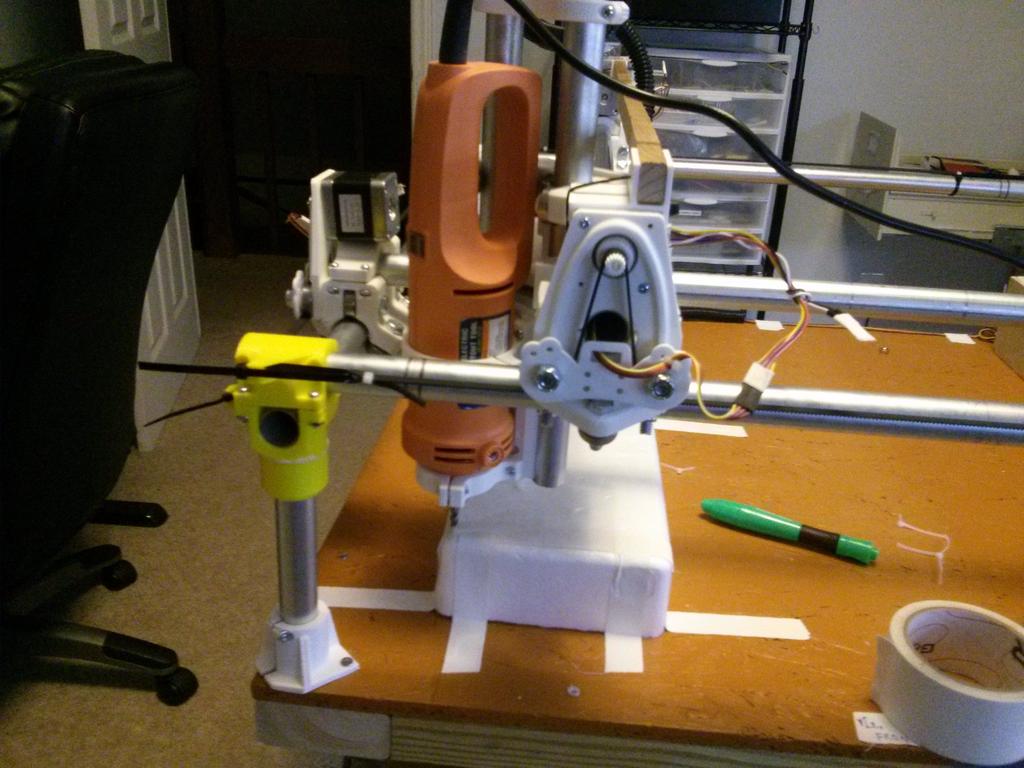
I 3D printed a pen holder to attach to the tool, so I can do ink-based tests while I work out the kinks. I did a dickbutt print on the same crappy foam, offsetting it a bit upward. The result is surprisingly good, given that the foam is nowhere near level, and I used the same program that assumes a 1/8″ endmill. Look at the solid ink on those eyes…nice!
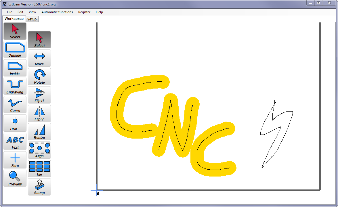
I strapped an incredibly crappy Harbor Freight Cutoff Tool to the MPCNC (related posts) thanks to this mount, and I was actually able to mill something! It worked! I crudly cut the hand-drawn letters “CNC” into the foam that the tool was packed in!
Now I just need to connect a power relay to automate the tool, add end-stops, learn to use the CNC software, learn to use good design software, possibly get better client software than Repetier Host, and add some kind of clamping mechanism to the table surface.
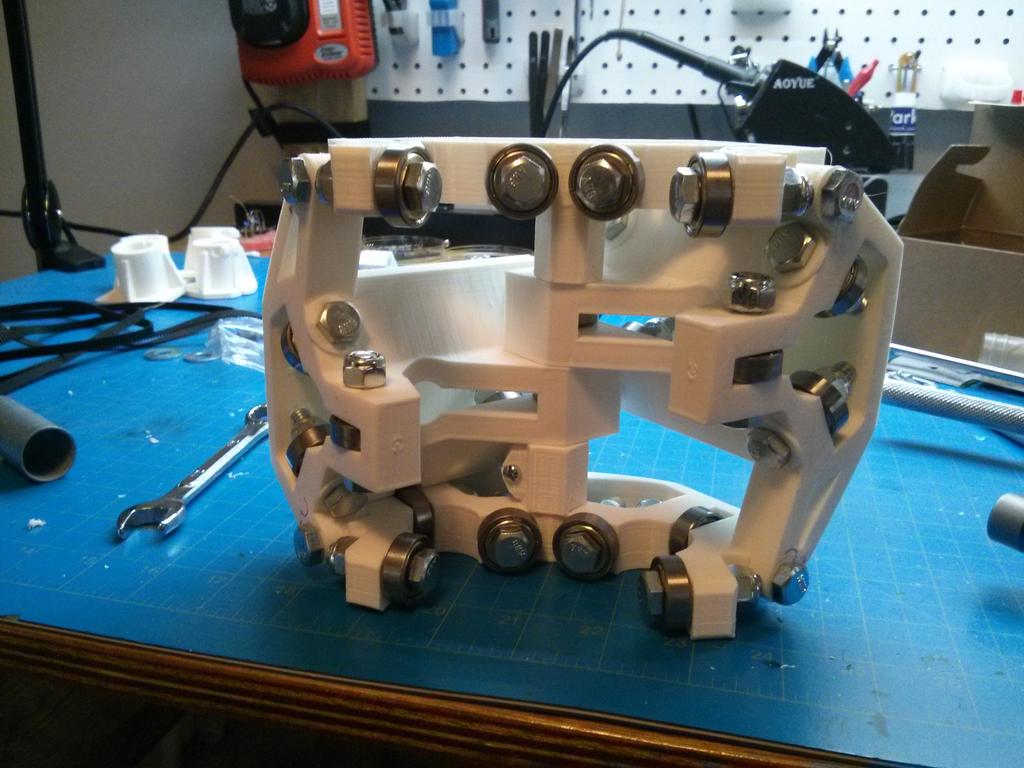
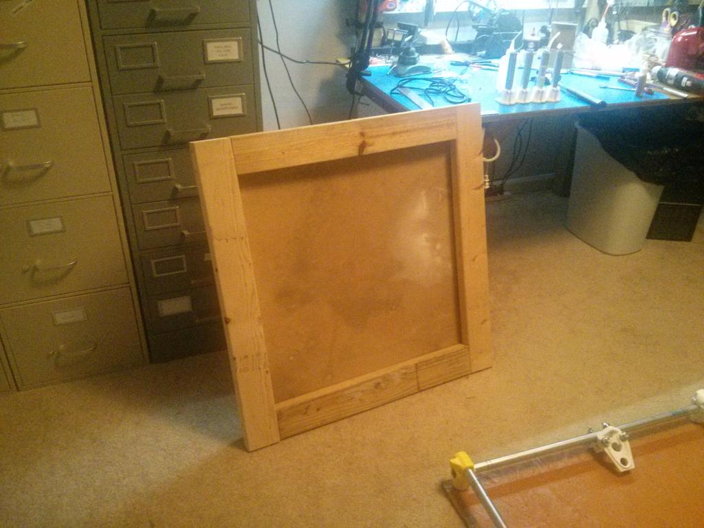
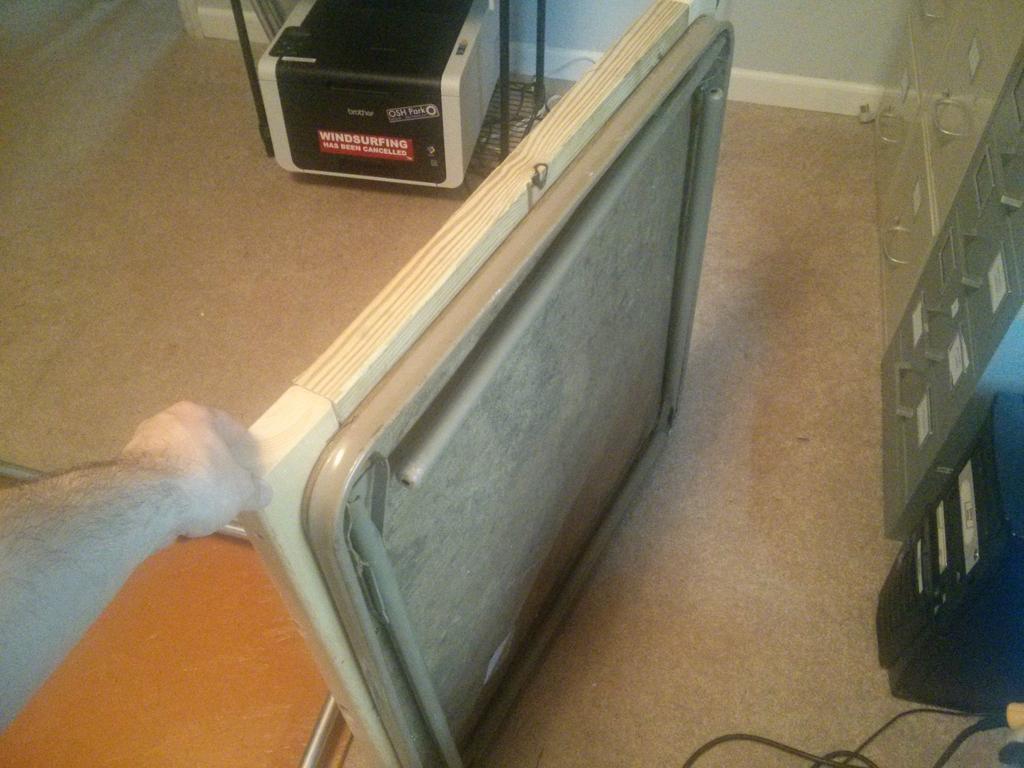
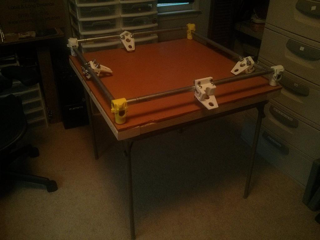
I haven’t taken many progress photos of the MPCNC because the build matches the assembly guide so well. It is MUCH better designed than the Prusa i3 design I fought with.
One difference from the stock guide is that I’ve mounted mine on a metal table with folding legs to make it portable.
I didn’t have much time to work on a side project, but I was able to clear one day’s schedule, so I woke up early and queued the music. I built just a “toaster bot” (meaning all it can do is drive — no other mechanisms), but the drive system is fairly nice, and it came together well. I’m going to make this a very quick overview post on the design and fabrication of the bot. Apologies, but I took zero pictures of the build process. Also, I’d show you a video of it, but I drive it my phone, which won’t record and let me drive at the same time. You can spot it rolling in the competition highlight video at the end of this post, though.
Mechanical:
The chassis and wheels are 3D printed. It uses a pair of gearmotors I got from Ax Man Surplus a while ago, which directly drive the main wheels. These wheels have a strip of mouse pad hot-glued to them for fantastic traction.
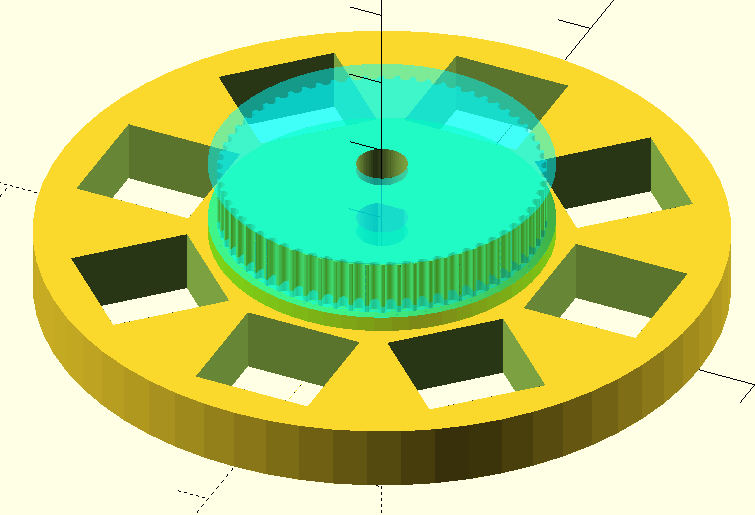
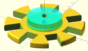
The secondary wheels are also driven by the motor via a GT2 belt; both wheel models include a GT2 pulley as part of their design. I found a way to fuse bulk GT2 belt into the necessary loops; I posted about that here.
The secondary wheels house a 608ZZ bearing held by a 5/16″ bolt. This is a neat trick that exploits the fact the 8mm inner diameter of the bearing is basically equal to 5/16″. The bearings allow the wheels to freely spin with little resistance or wobble. The sides of the wheel are rounded to allow these wheels to skid better during steering, and the gear-like pattern was to grip into irregular terrain. I originally had all four wheels covered in mousepad material, but it was impossible to turn, since this design relies on two of the wheels skidding horizontally. As to their construction, the main wheels are single pieces, with some diameter subtracted off to account for the mousepad material. The secondary wheels are two part — an outer wheel with a space for a bearing, and a pulley that screws into the wheel and also holds the pulley in place.
The secondary wheels are mounted into slots in the chassis, allowing you to tighten down the bolt and nut at varying degrees of tension. I found that having a tensioner was essential to dialing in correct performance, especially when I changed motors later on (see below).
The design of the chassis wasn’t very amenable to 3D printing, as the large flat area had a tendency to warp. One thing I added in anticipation of this were horizontal threaded rods for structure stability. This allowed me to correct any chassis flexing and add lots of rigidity cheaply.
I designed the chassis in Sketchup (which is definitely NOT the right tool for the job, but I know it well, and I haven’t made time to learn something better yet). The wheels were designed in OpenSCAD, as I needed to model the GT2 pulleys with correct geometry, and I was able to adapt existing code for this. I spent a fair bit of time modeling the motors, as it was a little challenging getting the hole placement using just digital calipers. In the end, I was able to get it exact with a little trigonometry.
I made proper standoffs for the electronics boards to screw into, but I had to abandon most of them since i didn’t account for the length of bolt on the secondary wheels. I ended up breaking off all my nice standoffs and just screwing the board into drilled holes. It holds just fine. The battery pack is unfortunately two-sided, so I couldn’t just bolt it down. It’s held in with a twist tie so I can get it loose to replace batteries when needed.
Once it was finished, it worked, but the motors were woefully underpowered. I was about to give up and leave it as-is until I found that the gearmotors I was using were apparently somewhat standard, as I was able to find strong 60RPM ones on Amazon with the exact same form factor and screw holes. I ordered them, and a drop-in replacement transformed it from an underpowered baby to a slow, methodical, but unstoppable beast.
Electrical:
It’s a fairly standard Arduino robot with some tweaks. First, I somehow didn’t have ANY Arduino motor controllers when I went to build it, and no time to wait for shipping. I did happen to have a single L298 motor control module from back before I understood shields, so there was some additional manual wiring of the Arduino to the motor module. On the plus side, this module is rated for way more power than the shield, in case I need it.
Also, the motor control module features its own 5V regulator, which was useful once a short circuit during a demo killed the one on board the Arduino. I was able to snip out the Arduino’s dead regulator and just wire the 5V line from the motor module to the Arduino, and it fired right up. (I also soldered on a replacement regulator, but that’s just so I could reuse the Arduino later if I need to.)
Commands are received via a cheap HC-06 bluetooth serial module connected into the analog in ports. (I used the analog ports because this is based on a design used by the TerrorBytes with the Arduino motor shield; the shield only exposes the analog ports, as the digital ones are all used by the shield itself.) I didn’t bother wiring the bluetooth RX line, as control is one-way, so it’s unneeded. Also, the device claims to only support 3.3V levels while the Arduino is 5V, so it might kill it? I’ve seen others feed this module 5V signals without issue, though. Better safe than sorry.
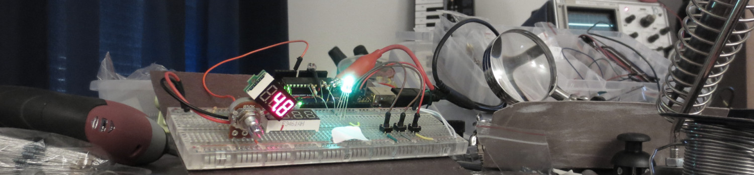
I also threw a cheap voltmeter on to monitor battery levels. This runs off the voltage it’s measuring, so it’s really easy.
Power was originally toggled by plugging/unplugging the battery minus to the Arduino ground pin, but I discovered by accident that the robot can drive when flipped upside down, and the pin was ripped from the wire while driving upside down throgh grass. As a result, there’s now an actual power switch, and all pins are hot glued in place.
Power simply comes from the 8xAA case, providing 12V.
Software
The initial version of the Arduino code was written by a TerrorBytes student; I simply adapted it to my wiring and robot design. The drive station software was initially a Python script designed to read gamepad values on a PC and send them over serial.
My “code” crammed into App Inventor
This worked fine, but I wanted to drive it from my phone, so I used Google App Inventor (now hosted at MIT) to make a simply joystick emulator. I ran into several issues doing this — App Inventor does not have any multi-touch support, so I couldn’t actually simulate two joysticks. Instead, I ended up having it do something that FIRST robotics calls “arcade drive”, where a single stick is used to input both steering (X axis) and power (Y axis). I actually ended up mining the control equations from wpilib, the library that runs on all FIRST Robotics Competition robots (see check_drive here for a python variant of the code, which I ported to App Inventor’s puzzle-piece coding system).
Timeline
Because I only had one day, everything was pipelined: 3D printing of pieces was continuous and done in parallel with design. I started with the motor mount, printing just enough to see if the motor could go on. While that printed, I did the wheels in OpenSCAD. When the motor mount prototype finished, I started a wheel printing while I did a test fit. I worked on the chassis design while wheels were printed/tested iteratively.
Finally, the chassis design was done, and I started the 2-hour print. I was concerned that chassis issues could sink me given how little time I had to dedicate to this, so I also designed a side-bracket variant of the chassis that I could bolt to wood; this would print faster if needed. In the end, however, I was able to cut and drill enough stuff on the initial printed chassis that I was able to make it work.
In the end, I was able to assemble all the bits and get basic movement by the end of the day. I had to wait overnight to be sure the belts I glued would cure, so I did cheat and spend a few minutes the next day mounting them.
Also, the drive software was initially a Python script designed by TerrorBytes students for use with a PC drive station. I developed the phone app for driving separately, taking care to design it to be backwards compatible with the Pythons script’s simple 4-axis protocol.
Result
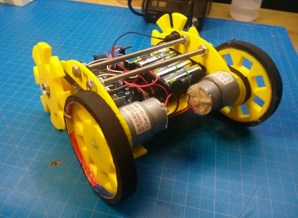
Here’s the final bot in all its glory:
It competed fairly well in the competition, making it to the first round of eliminations. Ultimately, it was defeated by robots built in more than one day…
See if you can spot it in the competition highlights reel:
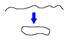
I was building a little robot, and I wanted belt-driven four-wheel drive using GT2 belt (an inexpensive timing belt common in 3D printers). The problem: I only had bulk GT2 belt, not closed loops (see extremely advanced diagram on right).
For my first attempt, I used end-slips to cut out the teeth from part of the belt, then super-glued it to the back of the other side. This works okay, but the joint was very inflexible owing to the near doubling of the thickness, and it eventually came apart after a few days use.
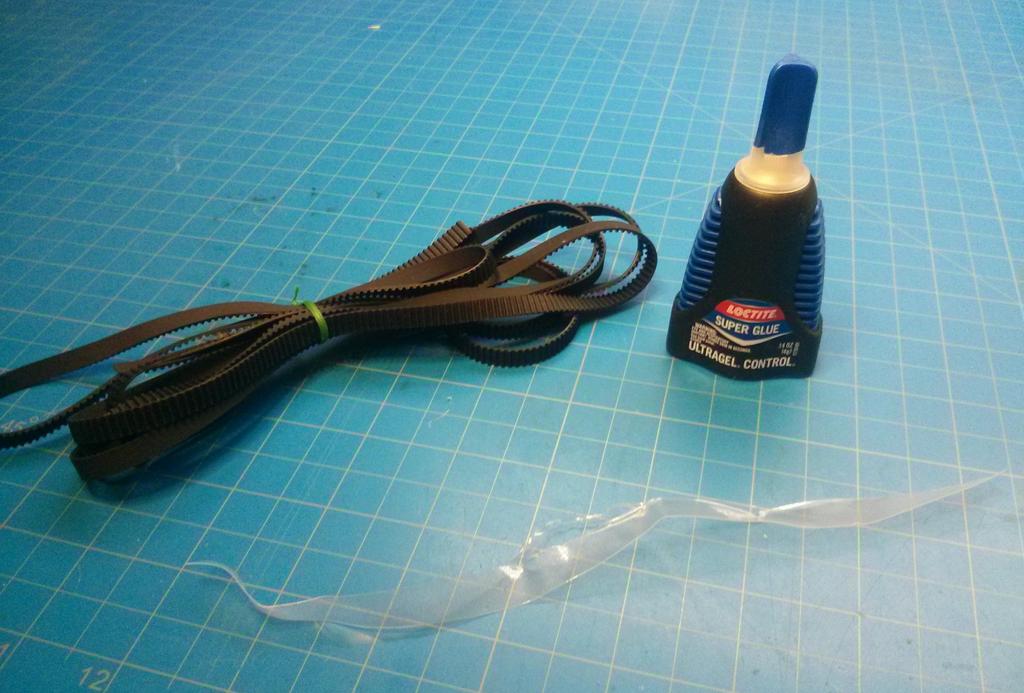
I’ve since found a better solution. What we need is a backing: a material I could adhere to the back of both sides of the belt, and which would be strong, flexible, and compatible with superglue.
I found such a substance in my trash can! When you buy 3D printing filament, it usually comes vacuum-sealed in clear plastic to keep it dry. The parts of this plastic that have been heat-pressed together are strong and flexible without stretching — it’s the perfect belt backing!
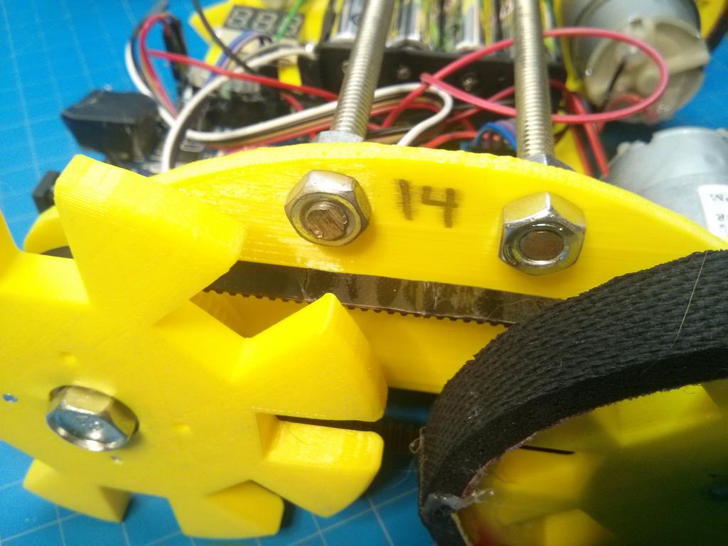
So I cut a narrow strip and super-glued it to the back of one end of the belt. Superglue dries hard, so I put down the glue in stripes so that the belt would still be flexible. After it dried a little, I glued the other end of the belt on, making sure to provide glue at the joint itself as well.
I let it dry under a weight for a few minutes, and the joint came out almost as flexible as the belt itself. The resulting bond has no give when stretched, goes over pulleys well, and survived the maximum tension I could put on the pulley by hand.
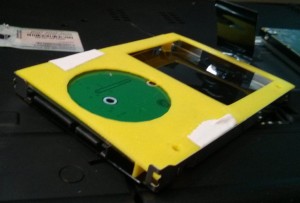
Pictures of belt on the end result (a little yellow robot):


 The secondary wheels are mounted into slots in the chassis, allowing you to tighten down the bolt and nut at varying degrees of tension. I found that having a tensioner was essential to dialing in correct performance, especially when I changed motors later on (see below).
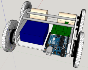 I made proper standoffs for the electronics boards to screw into, but I had to abandon most of them since i didn’t account for the length of bolt on the secondary wheels. I ended up breaking off all my nice standoffs and just screwing the board into drilled holes. It holds just fine. The battery pack is unfortunately two-sided, so I couldn’t just bolt it down. It’s held in with a twist tie so I can get it loose to replace batteries when needed.


