TinyBuddy: A host board for the ATTINY84

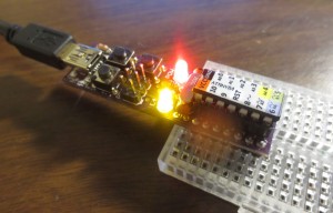
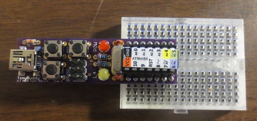
IMG_1902bI’m going to be making a large 7-segment display clock later, and I needed a control board for it.  Rather than purpose build something, I set out to make a generalized board I could reuse with various projects based on the Arduino-compatrible ATtiny84 microcontroller.

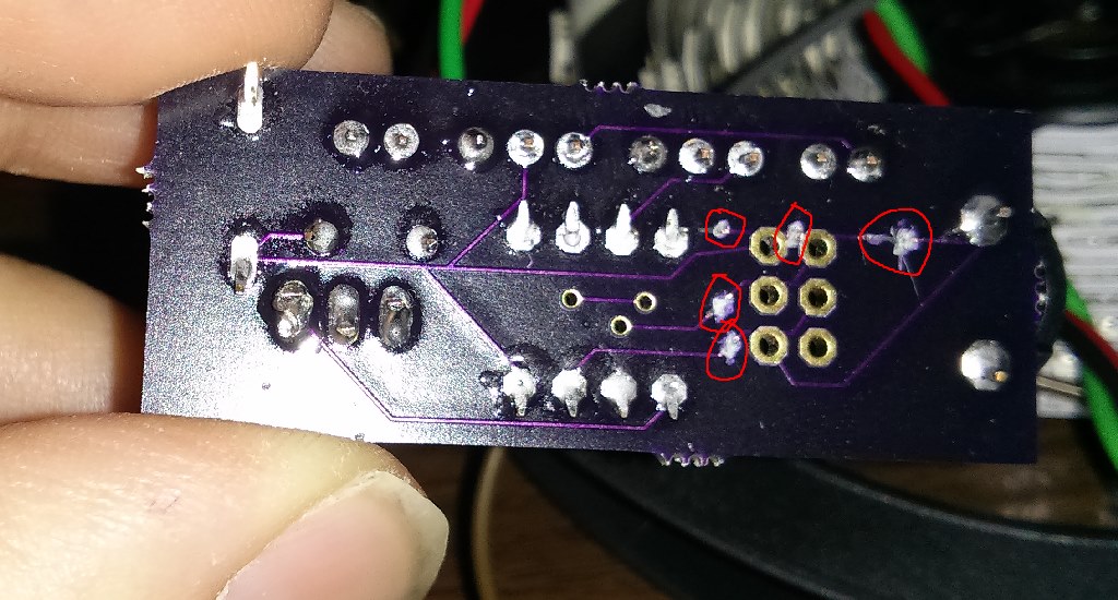
The result is the TinyBuddy: a general host PCB for the ATtiny84. Features two buttons (plus reset), a power LED, activity LED, 16MHz crystal for accurate timekeeping, and USB or DC barrel jack for power. The pins are one-to-one correlated to the pins of the bare chip, so it’s a drop in replacement on a breadboard.  While the prototype (pictured here) used micro-USB for power, I designed a second revision that uses entirely through-hole parts for easy construction. It can be fabricated for about $7 through OSH Park!

You can find the Eagle design files for it on github, or order it directly from OSH Park (Rev1 with micro USB, Rev2 with barrel jack).

IMG_1900bSome build history after the break.  Continue reading TinyBuddy: A host board for the ATTINY84

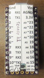
Teensy 3.1 label

IMG_1885bI just picked up a Teensy 3.1, which is an ARM development board that can speak Arduino.  OSH Park was running a special where I could tack one onto my order for a few bucks.  It’s pretty neat.

The only downside is that the design doesn’t have pin labels on the top of the board.  This makes it really tough to use in a breadboard.  To fix this, I made a label to stick to it to call out the pins — posting here in case someone on the internet could use such a thing.

Here’s the PDF, as well as the Microsoft Publisher source file.  Unlike the photo, the linked label has the name of the board written in text rather than in ballpoint pen.

Ax Clock Part 2

This is a guest post from my friend Rebecca on her adventures building her own Ax Clock. -Tyler
IMG_1379

This blog post came about because I saw Tyler’s Ax Clock post and wanted one for myself. He wrote a nice blog post about it, but I didn’t know enough to make it myself so I asked him to help me. As we were making the clock, Tyler asked me if I would like to make a guest post on his blog. I was not sure if this was a good idea because a) Tyler has already made a post about this same project and b) I know basically nothing about electronics or programming. This did not stop me from immediately agreeing to do it.

Full story after the break.  Continue reading Ax Clock Part 2

Engraver makes a good PCB trace cutter

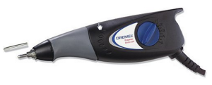
I have a ton of projects I haven’t documented on here. Sorry, internet.  For now, here’s this: I just discovered a useful tip. If you need to sever some PCB traces with precision, use an engraver like this one.

engraverI got some PCBs in and found out I had screwed up — multiple traces were inadvertently bridged. So I had to sever some of them to make the board work, some of which were very close together. The engraver worked awesomely. It’s like a high precision targeted PCB scalpel — I pulled up a trace that was a millimeter away from another.

Proof:engraved-pcb

Ax Man Clock

IMG_0402

Ax Man surplus in Minneapolis is a magical place.  They have tons and tons of electronic and industrial surplus, plus a bunch of just general weird crap.  It helps that the place is packed with the bizarre inventions of the owners and employees (robotic mannequins with mismatched limbs, motion sensing babies that cry when you walk by with a chilling robotic scream, etc.).

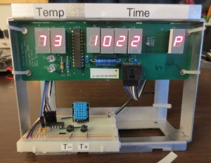
Last time I was up there, I found a board with a bunch of seven-segment displays, a chip, and a 6-pin connector.  I thought the chip might be an LED driver I could look up, so I took a $2 bet and bought it, figuring I might be able to reverse engineer it.

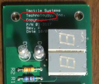
The chip turned out to be a common LED driver, the MAX7221.  I applied the circuit tracing technique I described earlier, and found that the connector easily mapped to power, ground, and signalling for the chip.  So I made a clock out of it.  Also, I spotted why the board was sent to surplus:

IMG_0396 typo

What a waste for Tactile Systems Technology…a whole run of boards fully populated, thrown out because of a silk screen typo :-).  That company is still around — they make medical gear, so I guess the thought of a life saving device with a typo was a non-starter.

Build directions after the break.  Continue reading Ax Man Clock

E-tweezers: a $6 way to make multimetering easier

IMG_0379b

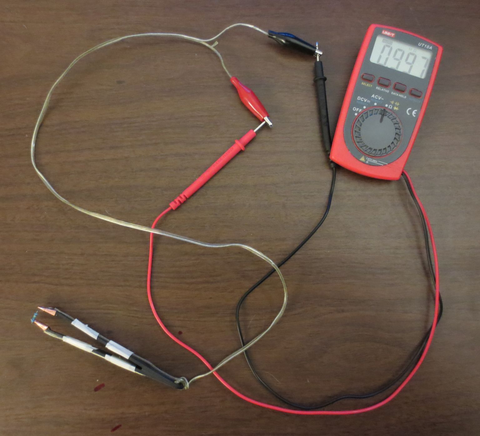
A while ago, I read a post about “Smart Tweezers” on Hack a Day, as well as a DIY version as well. These are good designs to measure components without trying to hold two probes and the component at the same time.  These designs are overkill (and overpriced) for what I do, though…I don’t need a whole meter built into my tweezers.

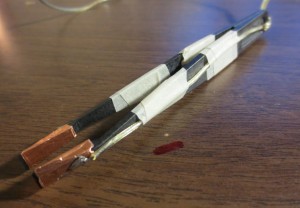
That inspired me to build this cheap hack: E-tweezers.  Basically, I just made the tips of some plastic tweezers conductive, and wired them down to some alligator clips to hook to my multimeter:

IMG_0386b

Build directions are after the break.

Continue reading E-tweezers: a $6 way to make multimetering easier

The Nickelphone

(Wow, just found out that this made Hack A Day, cool!)

I just finished the Nickelphone!  It’s a coin-based music keyboard. 15 nickels and 10 pennies act as touch sensors on a traditional 25-key piano-style layout. It can emit simple square wave tones through an onboard piezo buzzer, but its primary use is as a MIDI keyboard, so it can drive a full synthesizer (like FL Studio on PC). It’s based on an ATmega644 microcontroller, chosen because each key needs its own pin, and this chip has 32 data pins (8 of them analog inputs).  (Also, it happens to be the chip I got for free in when I placed my Atmel free sample order.)  It uses the “no extra parts” capacitive sensing method developed by Mario Becker and others.  For the MIDI output, I used the “last darned MIDI interface I’ll ever build” by Stephen Hobley (just the output part, which just uses one resistor).  The software is written in Arduino, with the “core” for the ATmega644 chip being adapted from the Sanguino project.  The Nickelphone was inspired by Linus Åkesson’s Chipophone and its follow-on, the bitbuf, both of which are totally awesome.

Read on for details…

Continue reading The Nickelphone

Nickelphone update

Here’s an update to the Nickelphone (previous post here). It’s still made out of 15 nickels and 10 pennies acting as touch sensors on a traditional 25-key piano-style layout. It now has MIDI output and can detect any number of simultaneous key presses, so it works great with a full synthesizer (like FL Studio)!

I still need to do a full write up, and make it a little more well-built.


The Nickelphone – work in progress

Here’s a work in progress video of my home-made musical instrument, the Nickelphone.


It’s a coin-based music keyboard.  15 nickels and 10 pennies act as touch sensors on a traditional 25-key piano-style layout.  It currently emits one tone at a time through a little piezo buzzer, but it will eventually emit MIDI signals so it can drive a full synthesizer (like FL Studio).  Based on an ATmega644 microcontroller and coded in Arduino with the CapacitiveSensor library for touch sensing.

I’ll do a full write-up here when it’s done.

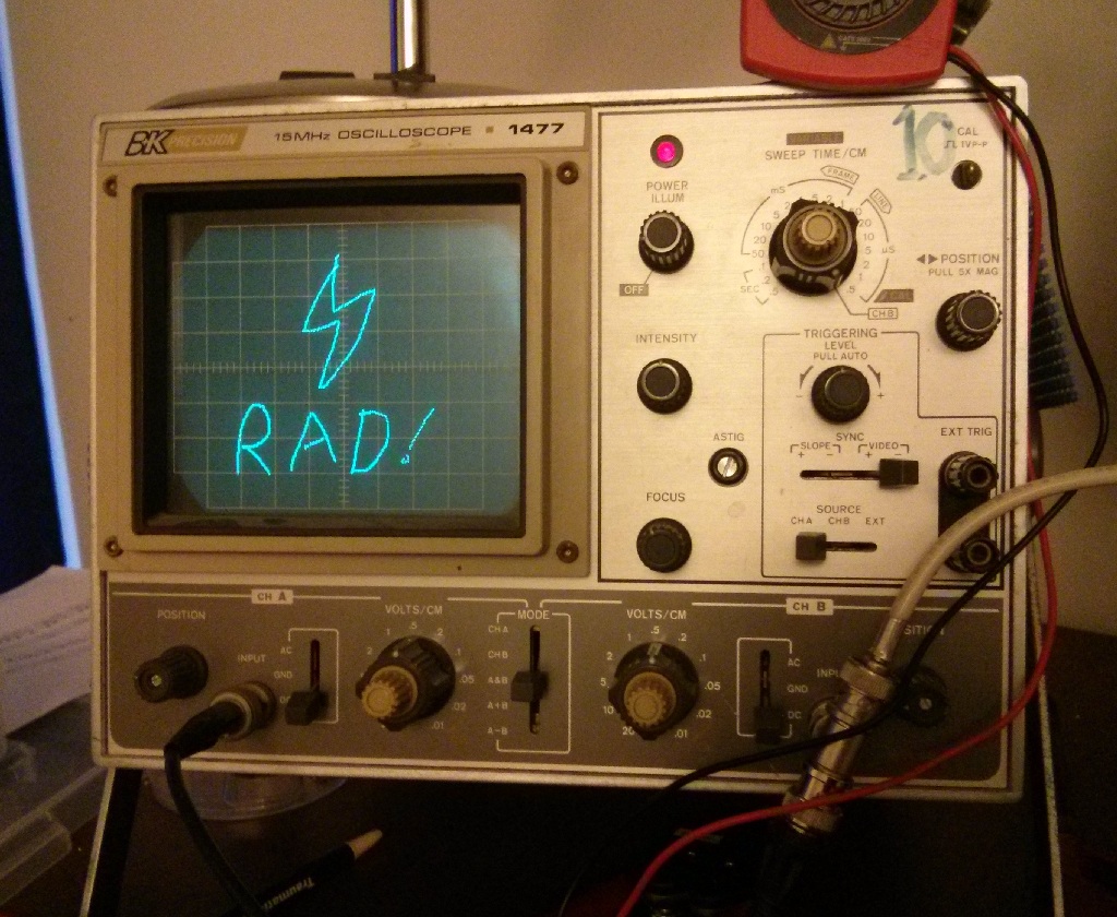
Draw anything on an oscilloscope

2013-09-21 10.15.01b

I have an old analog oscilloscope I got from university surplus, and it’s been more than enough for all the work I’ve done so far.

One thing I’ve wanted to do for a while was draw arbitrary stuff on it using X/Y mode, recreating the vector graphics systems of the past, especially stuff like the seminal Tennis for Two.  Unfortunately, a plain Arduino can’t output true analog signals–the analogWrite function just sets pulse-width modulation (PWM) so the pin is up x% of the time rather than truly being x% of the voltage.  So I needed a digital-to-analog converter (DAC).

I was originally going to build a R-2R DAC out of resistors, but that eats a ton of pins, so I wouldn’t be able to scale down to a smaller controller later if I wanted.

Instead, I decided on getting a dedicated serial DAC, which is an IC that receives the voltage level via serial digital communication, then outputs it.  Originally I tried to get a super-cheap audio DAC, the TDA1543, but the protocol for that is weird, and I got a non-standard “japanese interface” variant, and also I may have fried it.  Anyway, it didn’t work, so I got the much more standard MCP4802.

The MCP4802 is from the MCP48xx line (datasheet), with the model number indicating it has 8 bits of resolution and two independent channels.  It communicates over plain SPI, a well known standard with hardware support on Arduino.  I found a ready-made library for it here. (I had to fix one thing in it — it didn’t include SPI.h in its own header file. I also renamed CHANNEL_A/B to CH_A/B for brevity.)

I wired it as described here, and it worked perfectly.  With this, I hooked up the X and Y lines to the two outputs of the DAC, and set about drawing some stuff.  After getting it to draw a circle (x=cos(theta), y=sin(theta), scale output to 0..4095), I decided to draw some arbitrary stuff.

To encode the art, I wrote a small Processing app to let me mouse-draw some stuff, with the coordinates being saved to a file in CSV format.  Code:

PrintWriter output;

void setup()
{
  size(256,256);
  output = createWriter("positions.txt");
}

// x0=-1 means "the next click is the start of a new line segment"
int x0=-1,y0=-1;
int x,y;

void draw() {}

void mouseDragged() {
  x = mouseX;
  y = mouseY;
  output.println(String.format("%d,%d",x,(256-y)));
  output.flush();
  if (x0>=0) {
    line(x0,y0,x,y);
  }
  x0=x;
  y0=y;
}

void mouseReleased() {
  x0=-1;
}

So now I can draw stuff:
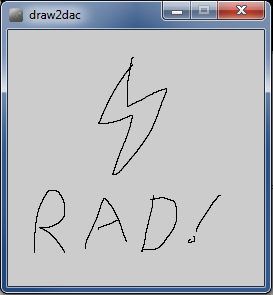
rad

I wrote a small Python app to convert the CSV list of coordinates to array declarations for Arduino. (I could have done this formatting in Processing directly, but that would have involved arrays and a save function, and I’m not very familiar with Processing yet, so this was faster.)  This code also drops every other coordinate to improve the refresh rate.

import fileinput

X=[]
Y=[]

every_n = 2 # we throw away every other pixel to improve the refresh rate

i=0
for line in fileinput.input():
	i += 1
	if i%every_n != 0: continue
	x,y = line.strip().split(",")
	X.append(x)
	Y.append(y)

print "byte X[] = {%s};" % ','.join(X)
print "byte Y[] = {%s};" % ','.join(Y)

I run it with:

  $ python pos2code.py positions.txt > rad.txt

I then dropped those two lines into the top of my Arduino program:

// MCPDAC relies on SPI.
#include
#include
#include

int i=0;

byte X[] = {...INSERT VALUES HERE...};
byte Y[] = {...INSERT VALUES HERE...};

void setup() {
  MCPDAC.begin(10,9); // CS pin, LDAC pin (latter only needded for x/y sync)

  MCPDAC.setGain(CH_A,HIGH); // Set the gain to "HIGH" mode - 0 to 4096mV.
  MCPDAC.setGain(CH_B,HIGH); // Set the gain to "HIGH" mode - 0 to 4096mV.

  MCPDAC.shutdown(CH_A,false);
  MCPDAC.shutdown(CH_B,false);
}

void loop() {
  int x,y;

  x = X[i]*16; // *16 to go from 0..255 to 0..4095
  y = Y[i]*16;

  MCPDAC.setVoltage(CH_A,x&0x0fff);
  MCPDAC.setVoltage(CH_B,y&0x0fff);
  MCPDAC.update(); // this toggles LDAC, actually changing the outputs -- you can omit this if not using the LDAC pin (leaving it grounded)

  i++;
  if (i>=sizeof(X)) i=0; // wrap around the array

}

The program cycles through the values, sending them to the MCP4802, thus driving the oscilloscope, which was set to XY mode.  Now I can play with the code above to start trying out some effects, like this “crawling ant” pattern:

My setup:
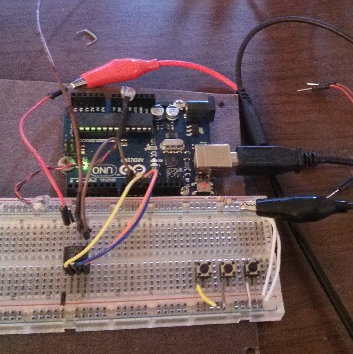
2013-09-21 09.43.28c